ENGINE PERFORMANCE
4.0L
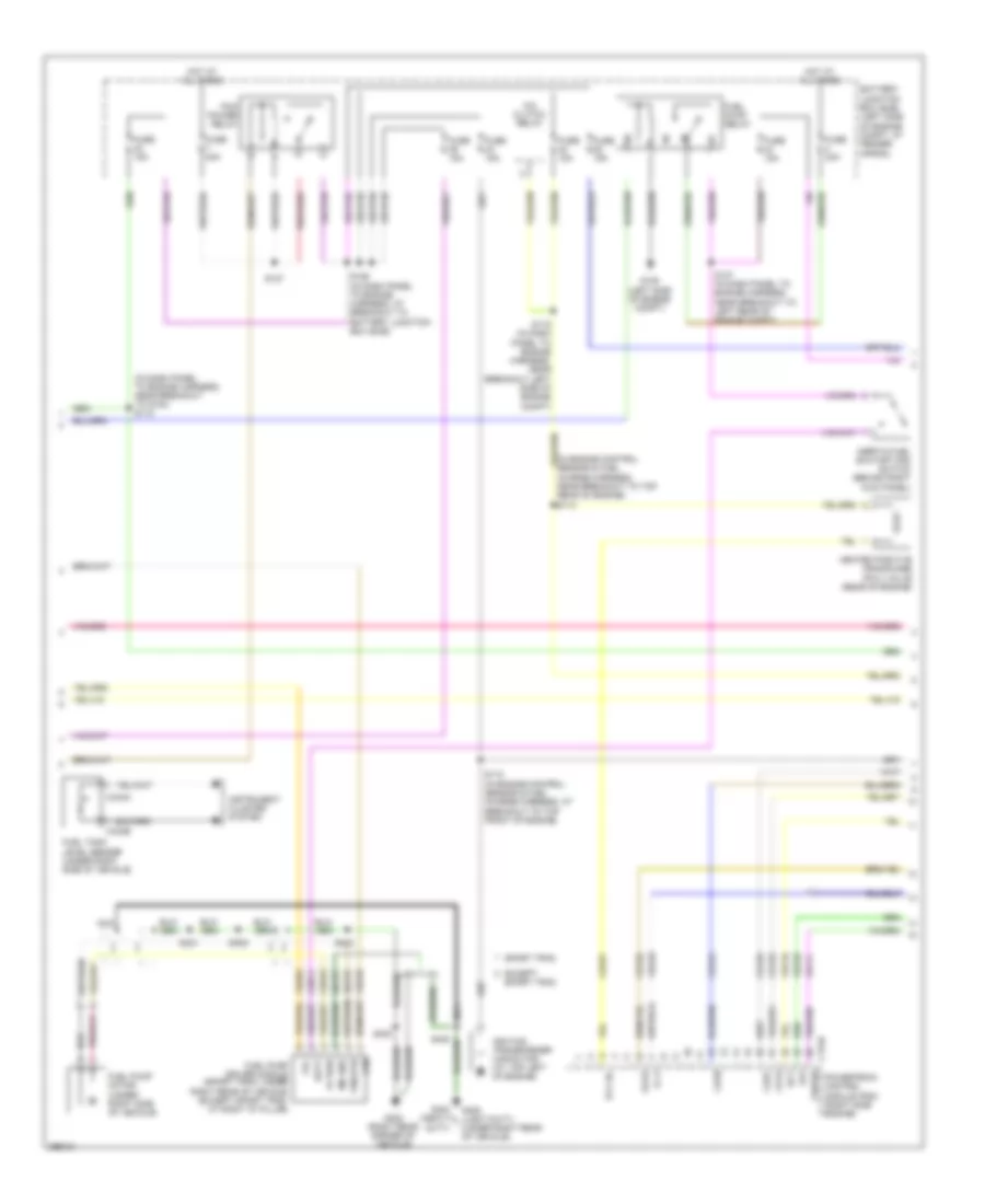
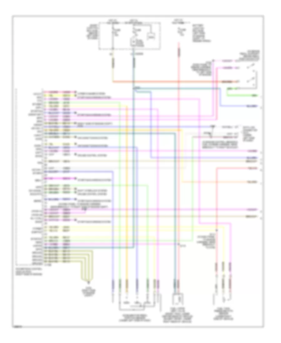
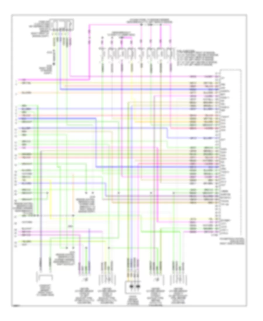
4.0L, Engine Performance Wiring Diagram (1 of 5) for Ford Explorer 2009

List of elements for 4.0L, Engine Performance Wiring Diagram (1 of 5) for Ford Explorer 2009:
- (in dash panel to engine harness, near breakout to left side of engine compt)
- (in dash panel to engine harness, near breakout to right front of vehicle)
- (right side of engine compt) g106
- Accelerator pedal position sensor (under left side of dash)
- Accr
- Accs
- Acds1
- Acpt
- Air conditioning system
- App1
- App2
- App3
- Battery junction box (bjb) (left side of engine compt, at fender apron)
- Bpp
- Bps
- Brake pedal position switch (on brake pedal support)
- C175b
- C2280e
- Canister vent solenoid (sport trac: under center rear of vehicle) (except sport: under right rear of vehicle)
- Canv
- Cbb39
- Ccs09
- Cdc10
- Cdc12
- Cdc15
- Cdc38
- Ce114
- Ce237
- Ce517
- Ces09
- Cet34
- Ch302
- Ch423
- Ch443
- Cruise control system
- Csgnd
- Data link connector (dlc) (under left side of dash)
- Etcref
- Etcref3
- Etcrtn
- Feps
- Fpc
- Fpm
- Ftp
- Ftpref
- Fuel pump diode
- Fuel tank pressure (ftp) sensor (under right side of vehicle)
- Fuse 10a
- Fuse 15a
- Fuse 2a
- G106 (right side of engine compt)
- Gd113
- Genac
- Genli
- Ground
- Hot at all times
- Hot in start or run
- Hs can+
- Hs can-
- Isp-r
- Kapwr
- Le136
- Le137
- Le424
- Od cancel
- Pc mrc
- Power steering pressure switch (top left front of engine)
- Powertrain control module (pcm) (right side engine)
- Pspsw
- Re136
- Re137
- Re407
- Res08
- S114 (in dash panel to engine harness, near breakout to g106)
- S116
- S117
- S121
- S121 (dash panel to engine harness, near breakout to left side of radiator)
- S122
- S124
- Sbb24
- Sbp22
- Sccs
- Sccs rtn
- Shift interlock system
- Sigrtn
- Smart junction box (sjb) (behind left side of dash)
- Smc
- Smcs
- Smr/start
- Sns
- Starting/charging system
- Vdb04
- Vdb05
- Vdb09
- Ve225
- Ve518
- Ve701
- Ve702
- Ve703
- Ve922
- Ves10
- Vh433
- Vmc05
- Vpwr
- Vs out
- Wiper/washer system
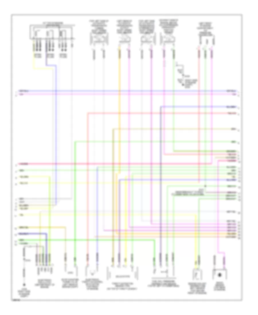
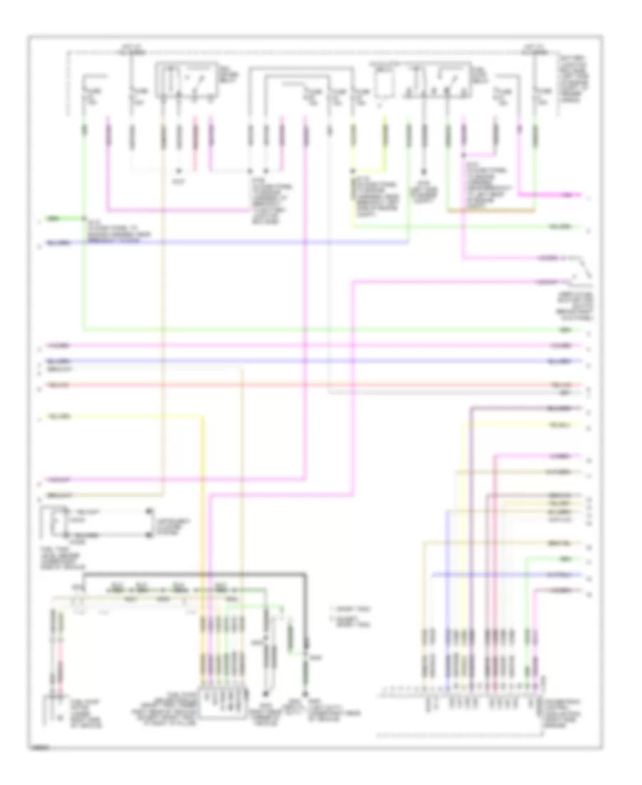
4.0L, Engine Performance Wiring Diagram (2 of 5) for Ford Explorer 2009
List of elements for 4.0L, Engine Performance Wiring Diagram (2 of 5) for Ford Explorer 2009:
- (in dash panel to engine harness, near breakout to g104) s118
- (in engine control sensor & fuel charge harness, near breakout to top rear of engine) s113
- A/c clutch relay
- Batt
- Battery junction box (bjb) (left side of engine compt, at fender apron)
- C175e
- C434a
- C434b
- Cd1a
- Cd2c
- Cd3b
- Ce123
- Ce124
- Ce125
- Ce132
- Ce321
- Ce515
- Ce911
- Ect
- Evap
- Except sport trac
- Fc-v
- Fp pwr
- Fpc
- Fpm
- Fpm rtn
- Frt
- Fuel pump driver module (sport trac: under right rear of vehicle) (except sport trac: at right "d" pillar)
- Fuel pump motor (under right side of vehicle)
- Fuel pump relay
- Fuel tank level sensor (under right side of vehicle)
- Fuse 15a
- Fuse 30a
- Fuse 40a
- G105 (left side of engine compt)
- G402 (right rear corner of vehicle)
- G404 (heavy duty)
- G405 (light duty) (under right rear of vehicle)
- Gd151
- Heated positive crankcase (pcv) valve (rear of engine)
- Hot at all times
- Ignition transformer capacitor (at top left of engine)
- Inertia fuel shutoff (ifs) switch (behind right kick panel)
- Instrument cluster system
- Le111
- Md gnd
- Nca
- Pcm power relay
- Pcv hc
- Powertrain control module (pcm) (right side engine)
- Re515
- S110 (in engine control sensor & fuel charge harness, at breakout to top front of engine)
- S119 (in dash panel to engine harness, near breakout left side of engine compt)
- S126 (in dash panel to engine harness, at breakout to battery junction box (bjb))
- S127
- S137 (in dash panel to engine harness, near breakout to left rear of engine compt)
- S400
- S403
- S405
- S421
- S430
- Sport trac
- Vbpwr
- Ve225
- Ve518
- Ve716
- Ve728
- Vec03
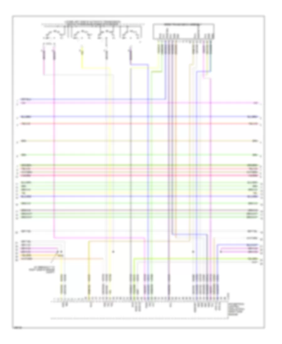
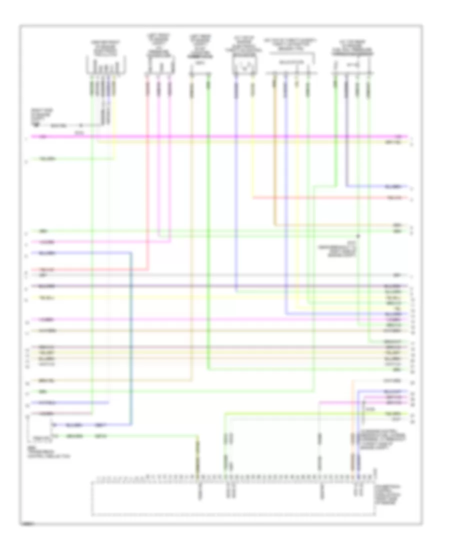
4.0L, Engine Performance Wiring Diagram (3 of 5) for Ford Explorer 2009
List of elements for 4.0L, Engine Performance Wiring Diagram (3 of 5) for Ford Explorer 2009:
- (at top of engine) ignition coil
- (left front of engine compartment) a/c pressure transducer
- (left rear of automatic transmission) output shaft speed (oss) sensor
- (on right side of engine, behind a/c compressor) crankshaft position sensor
- (on top of throttle body)
- (right side of engine compt) g106
- (top center front of engine)
- (top left side of automatic transmission) intermediate shaft speed (iss) sensor
- (top left side of automatic transmission) turbine shaft speed (tss) sensor
- Acpt
- Electronic fan clutch (center front of engine)
- Electronic throttle control (etc) motor (top front of engine)
- Engine coolant temperature (ect) sensor
- Evap canister purge valve (left rear of engine compt)
- Fcv
- Fss
- Fuel rail pressure/ temperature sensor (top of left cylinder head)
- G106 (right side of engine compt)
- Gnd
- Knock sensor (top rear of engine)
- Nca
- S103
- S107 (near breakout to right cylinder head valve cover)
- S109
- Sig rtn
- Solid state
- Spark plugs
- Throttle position sensor (tps)
- Vbpwr
- Vpwr
- Vref
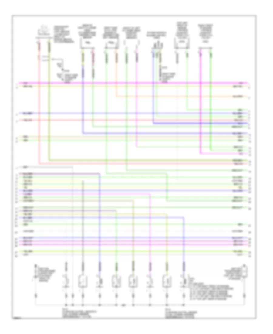
4.0L, Engine Performance Wiring Diagram (4 of 5) for Ford Explorer 2009
List of elements for 4.0L, Engine Performance Wiring Diagram (4 of 5) for Ford Explorer 2009:
- (at breakout to right side of engine compt)
- (lower left side of automatic transmission) digital transmission range (dtr) sensor
- 5r55s transmission assembly
- C175t
- Ce233
- Ce234
- Ce418
- Cet05
- Cet06
- Cet07
- Cet18
- Cet19
- Cet44
- Cet45
- Ho2s 12
- Ho2s 22
- Htr 12
- Htr 22
- Iss
- Oss
- Pca
- Pcb
- Pcc
- Powertrain control module (pcm) (right side engine)
- Pwr sol
- Re406
- Ret04
- S106
- Sigrtn tft
- Sigrtnt
- Ssa
- Ssb
- Ssc
- Ssd
- Tcc
- Tft
- Tr1
- Tr2
- Tr3a
- Tr4
- Tss
- Ve731
- Ve733
- Ve739
- Vet27
- Vet28
- Vet29
- Vet30
- Vet31
- Vet33
4.0L, Engine Performance Wiring Diagram (5 of 5) for Ford Explorer 2009
List of elements for 4.0L, Engine Performance Wiring Diagram (5 of 5) for Ford Explorer 2009:
- (in engine control sensor & fuel charge harness, near breakout to right cylinder head) s104
- C175e
- Camshaft position sensor (on front of left cylinder head)
- Cbb42
- Ce133
- Ce205
- Ce206
- Ce207
- Ce208
- Ce209
- Ce210
- Ce235
- Ce236
- Ce412
- Ce426
- Ckp+
- Ckp-
- Cmp1
- Dpfe
- Egr system module (top of engine)
- Etcref
- Etcrtn
- Evr
- Frp
- Fss
- Fuel injectors (1, 2 & 3: at top right front of engine) (4, 5 & 6: at top left front of engine)
- G106 (right side of engine compt)
- Heated oxygen sensor (ho2s) 11 (in right exhaust pipe, before catalytic converter)
- Heated oxygen sensor (ho2s) 12 (in right exhaust pipe, after catalytic converter)
- Heated oxygen sensor (ho2s) 21 (in left exhaust pipe, before catalytic converter)
- Heated oxygen sensor (ho2s) 22 (in right exhaust pipe, after catalytic converter)
- Ho2s 11
- Ho2s 21
- Htr 21
- Htr-11
- Iat
- Inj1
- Inj2
- Inj3
- Inj4
- Inj5
- Inj6
- Ks+
- Ks-
- Le134
- Le423
- Maf
- Mafrtn
- Map
- Mass air flow/intake air temperature (maf/iat) sensor (right front of engine compt)
- Powertrain control module (pcm) (right side engine)
- Re134
- Re135
- Re320
- Re323
- Re405
- S100 (in engine control sensor & fuel charge harness, near breakout to right exhaust)
- S103
- S105 (at breakout to right side of engine compt)
- Sigrtne
- Tacm -
- Tacm p
- Tp1 ns
- Tp2-ps
- Ve706
- Ve711
- Ve713
- Ve727
- Ve735
- Ve737
- Ve740
- Ve801
- Ve803
- Ve807
- Ve818
- Ve819
- Vec10
- Vrefe
4.6L
4.6L, Engine Performance Wiring Diagram (1 of 5) for Ford Explorer 2009
List of elements for 4.6L, Engine Performance Wiring Diagram (1 of 5) for Ford Explorer 2009:
- (in dash panel to engine harness, near breakout to right side of engine compt)
- (in engine control sensor & fuel charge harness, near breakout to right exhaust)
- (on brake pedal support) brake pedal position switch
- (right side of engine compt) g106
- Accelerator pedal position sensor (under left side of dash)
- Accr
- Acds1
- Acpt
- Air conditioning system
- App1
- App2
- App3
- Battery junction box (bjb) (left side of engine compt, at fender apron)
- Bpp
- Bps
- C175b
- C2280e
- Cbb39
- Ccb08
- Cdc10
- Cdc12
- Cdc15
- Cdc35
- Cdc38
- Ce114
- Ce237
- Ce517
- Ces09
- Cet34
- Ch302
- Ch423
- Cruise control system
- Csgnd
- Data link connector (dlc) (under left side of dash)
- Etcref
- Etcrf3
- Etcrtn2
- Etcrtn3
- Feps
- Fpc
- Fpm
- Ftp
- Ftpref
- Fuel pump diode
- Fuel tank pressure (ftp) sensor (under right side of vehicle)
- Fuel vapor vent valve (sport trac: under center rear of vehicle) (except sport: under right rear of vehicle)
- Fuse 10a
- Fuse 15a
- Fuse 2a
- G106 (right side of engine compt)
- Gd113
- Genli
- Genrc
- Ground
- Hot at all times
- Hot in start or run
- Hs can +
- Hs can -
- Isp-r
- Kapwr
- Le136
- Le137
- Le424
- Od cancel
- Powertrain control module (pcm) (right side of engine)
- Re136
- Re137
- Re407
- Res08
- Rly ctrl
- S101
- S102
- S114 (in dash panel to engine harness, near breakout to g106)
- S116
- S117
- S121
- S128 (dash panel to engine harness, near breakout to left side of engine)
- Sbb24
- Sccs
- Sccs rtn
- Shift interlock system
- Sigrtnc
- Smart junction box (sjb) (behind left side of dash)
- Smc
- Smcs
- Smr/start
- Sns
- Starting/charging system
- Vapnt
- Vdb04
- Vdb05
- Vdb09
- Ve225
- Ve518
- Ve701
- Ve702
- Ve703
- Ve922
- Ves10
- Vh433
- Vmc05
- Vpwr1-a
- Vpwr1-b
- Vs out
- Wiper/washer system
4.6L, Engine Performance Wiring Diagram (2 of 5) for Ford Explorer 2009
List of elements for 4.6L, Engine Performance Wiring Diagram (2 of 5) for Ford Explorer 2009:
- A/c clutch relay
- Batt
- Battery junction box (bjb) (left side of engine compt, at fender apron)
- C175e
- C434a
- C434b
- Cda
- Cdb
- Cdc
- Cdd
- Cde
- Cdf
- Cdg
- Cdh
- Ce132
- Ce303
- Ce304
- Ce305
- Ce306
- Ce307
- Ce308
- Ce309
- Ce310
- Ce515
- Ce911
- Evap
- Except sport trac
- Fc v
- Fp pwr
- Fpc
- Fpm
- Fpm rtn
- Frt
- Fuel pump driver module (sport trac: under right rear of vehicle) (except sport trac: at right "d" pillar)
- Fuel pump motor (under right side of vehicle)
- Fuel pump relay
- Fuel tank level sensor (under right side of vehicle)
- Fuse 15a
- Fuse 30a
- Fuse 40a
- G105 (left side of engine compt)
- G402 (right rear corner of vehicle)
- G404 (heavy duty)
- G405 (light duty) (under right rear of vehicle)
- Gd151
- Hot at all times
- Inertia fuel shutoff (ifs) switch (behind right kick panel)
- Instrument cluster system
- Le111
- Md gnd
- Nca
- Pcm power relay
- Powertrain control module (pcm) (right side engine)
- Re515
- S118 (in dash panel to engine harness, near breakout to g104)
- S126 (in dash panel to engine harness, at breakout to battery junction box (bjb))
- S127
- S137 (in dash panel to engine harness, (near breakout to left rear of engine compt)
- S400
- S403
- S405
- S421
- S430
- Sport trac
- Vbpwr
- Ve225
- Ve518
- Ve728
- Vec03
4.6L, Engine Performance Wiring Diagram (3 of 5) for Ford Explorer 2009
List of elements for 4.6L, Engine Performance Wiring Diagram (3 of 5) for Ford Explorer 2009:
- (at top of engine) electronic throttle control (etc) motor
- (at top rear of engine) fuel rail pressure transducer sensor
- (center front of engine) electronic fan clutch
- (in engine control sensor & fuel charge harness, at breakout to right side of engine compt)
- (left front of engine compt) a/c pressure transducer
- (left rear of engine compt) evap canister purge valve
- (on top of throttle body) throttle position sensor (tps)
- (right side
- 6r60 transmission control module (tcm)
- Acpt
- C175t
- Ce233
- Ce234
- Ce517
- Cet40
- Fcv
- Fss
- G106
- Gnd
- Ho2s 12
- Ho2s 22
- Htr 12
- Htr 22
- Of engine compt)
- Powertrain control module (pcm) (right side of engine)
- Re406
- S103
- S106
- S107 (near breakout to right side of engine compt)
- Sig rtn
- Sigrtnt
- Solid state
- Trsw pn
- Trsw-pn
- Vbpwr
- Ve731
- Ve733
- Vpwr
- Vref
4.6L, Engine Performance Wiring Diagram (4 of 5) for Ford Explorer 2009
List of elements for 4.6L, Engine Performance Wiring Diagram (4 of 5) for Ford Explorer 2009:
- (front of left cylinder head) camshaft position sensor 2
- (rear of right cylinder head) cylinder-head temperature sensor
- (right front of engine) variable camshaft timing (vct) valve 1
- (right side of engine compt) g106
- (right side of oil pan) engine oil temperature (eot) sensor
- (top left front of engine) variable camshaft timing (vct) valve 2
- Coil on plugs (cop) (1: at top right front of engine) (2, 3: at top right center of engine) (4: at top right rear of engine) (5: at top left front of engine) (6, 7: at top left center of engine) (8: at top left rear of engine)
- Crankshaft position (ckp) sensor (lower right front of engine, behind a/c compressor)
- Gnd
- Ignition transformer capacitor 1 (top right front of engine)
- Ignition transformer capacitor 2 (top left side of engine)
- Imrc
- Intake manifold runner control (imrc)
- S103
- S109
- S110 (in engine control sensor & fuel charge harness, near breakout to c139)
- S112 (in engine control sensor & fuel charge harness, near breakout to c133)
- Vpwr
4.6L, Engine Performance Wiring Diagram (5 of 5) for Ford Explorer 2009
List of elements for 4.6L, Engine Performance Wiring Diagram (5 of 5) for Ford Explorer 2009:
- (engine control sensor & fuel charge harness, near breakout to c1442) s108
- (in dash panel to engine harness, near breakout to left rear of engine) s111
- (near breakout to right cylinder head) s104
- C175e
- Camshaft position sensor 1 (front right cylinder head)
- Ce205
- Ce206
- Ce207
- Ce208
- Ce209
- Ce210
- Ce211
- Ce212
- Ce235
- Ce236
- Ce315
- Ce412
- Ce421
- Ce422
- Ce426
- Cht
- Ckp+
- Ckp-
- Cmp1
- Cmp2
- Eot
- Etcref1
- Etcrtn1
- Frp
- Fss
- Fuel injectors (1: at top right front of engine) (2,3: at top right center of engine) (4: at top right rear of engine) (5: at top left front of engine) (6,7: at top left center of engine) (8: at top left rear of engine)
- G106 (right side of engine compt)
- Heated oxygen sensor (ho2s) 11 (in right exhaust pipe, before catalytic converter)
- Heated oxygen sensor (ho2s) 12 (in right exhaust pipe, after catalytic converter)
- Heated oxygen sensor (ho2s) 21 (in left exhaust pipe, before catalytic converter)
- Heated oxygen sensor (ho2s) 22 (in left exhaust pipe, after catalytic converter)
- Ho2s 11
- Ho2s 21
- Htr 11
- Htr 21
- Iat
- Imrc
- Inj 5
- Inj1
- Inj2
- Inj3
- Inj4
- Inj6
- Inj7
- Inj8
- Knock sensor (top rear of engine)
- Ks+
- Ks-
- Le134
- Le423
- Maf
- Mafrtn
- Mass air flow/intake air temperature (maf/iat) sensor (right front of engine compt)
- Powertrain control module (pcm) (right side of engine)
- Re134
- Re135
- Re320
- Re323
- Re324
- Re405
- S100 (engine control sensor & fuel charge harness, near breakout to right exhaust)
- S103
- S105 (engine control sensor & fuel charge harn, breakout to right side of engine compt)
- Sigrtne
- Tacm n
- Tacm p
- Tan
- Tp1 ns
- Tp2-ps
- Vct1
- Vct2
- Ve706
- Ve707
- Ve711
- Ve712
- Ve717
- Ve727
- Ve735
- Ve737
- Ve740
- Ve801
- Ve802
- Ve807
- Ve818
- Ve819
- Vec10
- Vrefe