ENGINE PERFORMANCE
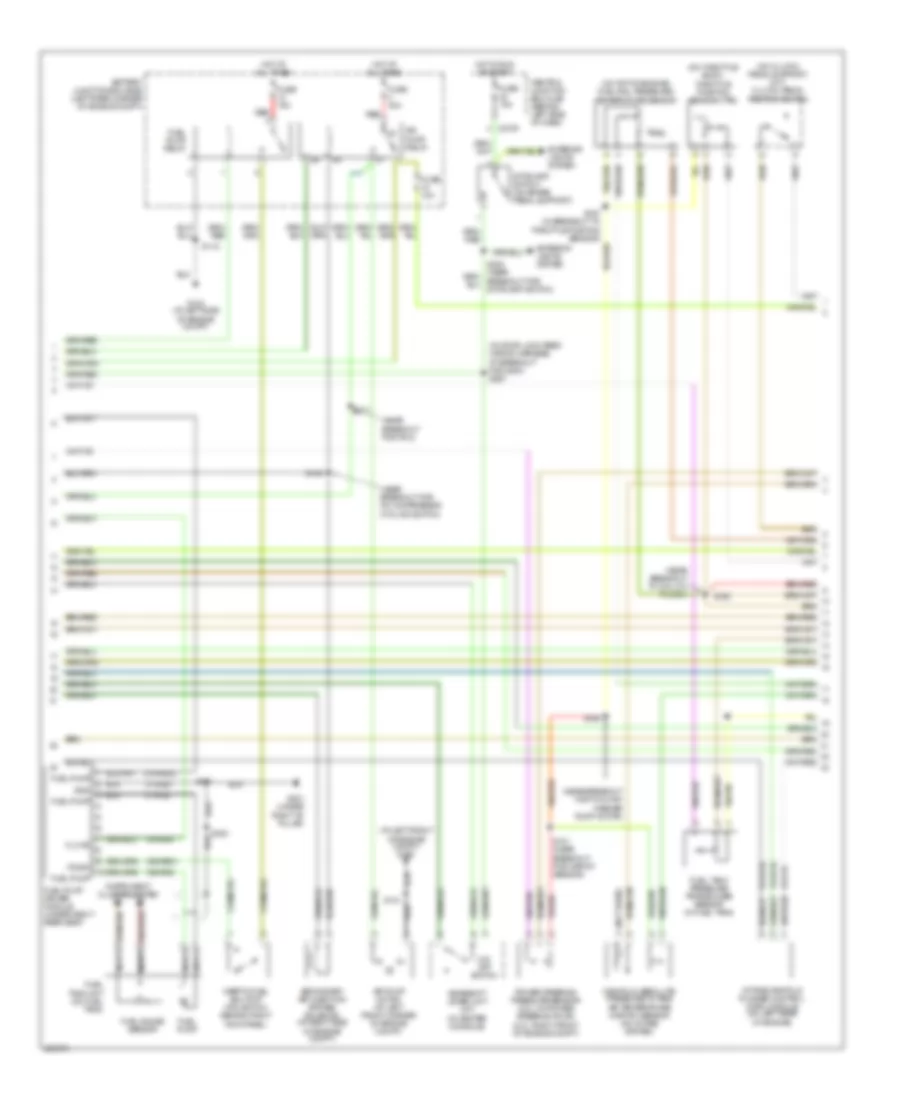
Engine Performance Wiring Diagram (1 of 4) for Ford Focus ZX3 S 2005

List of elements for Engine Performance Wiring Diagram (1 of 4) for Ford Focus ZX3 S 2005:
- (near breakout for dlc)
- 10-gl37
- 15-re16
- 15-re8
- 15-re8a
- 15s-re10a
- 15s-re13
- 15s-re8
- 15s-ta21
- 29-re14
- 30-re8
- 31-re8a
- 31s-bb16
- 31s-fa11
- 31s-gl6
- 31s-pa17
- 31s-pa21
- 31s-pa7
- 31s-re32
- 31s-rh1
- 31s-rl25
- 4-ec7
- 5-ec7
- 8-ce10
- 8-gl37
- 8-pa13
- 8-re22
- 8-rj13
- 8-rj17
- 8-rj22
- 9-re8
- 9-rj22
- 91-re8
- 91-re8a
- 91-re8b
- 91-rj16
- 91s-rl3
- A/c clutch relay
- A/c clutch rly
- A/c press sw
- Acc
- Air conditioning system
- Air pump rly
- Anti-theft system
- Battery
- Battery junction box (bjb) (left rear corner of engine compt)
- Battery junction box)
- C175b
- C270b
- C270e
- Can h
- Can l
- Central junction box (cjb) (behind left side of dash)
- Computer data lines system
- Cooling fans system
- Cruise control system
- Dual pressure switch (at right front of engine compt)
- Eng cool fan
- Engine cooling fan relay
- Evap canister purge valve (rear side of engine compt)
- Evap purge
- Evap vent
- Evaporative emission (evap) canister vent valve (under rear of vehicle)
- Feps
- Ftp sens
- Fuel pump
- Fuse 10a
- Fuse 20a
- Fuse 30a
- G103 (at left side of engine compt)
- G202 (at right "a" pillar)
- Ground
- Hi cool fan
- High speed fan control relay
- Hot at all times
- Ignition relay
- Ignition switch
- Imrc module
- Intake air temp
- Lo cool fan
- Lock
- Low speed cooling fan relay a
- Low speed cooling fan relay b
- Maf sens
- Maf sens sig
- Mass air flow (maf) sensor (on intake system)
- Off
- Overdrive sig
- Passive anti-theft transceiver module (on upper right side of steering column)
- Pats ind
- Pcm power diode
- Power hold relay
- Powertrain control module (pcm) (behind right side of dash, at base of "a" pillar)
- Psp sens
- Pwr hold rly
- Red
- Run
- Rx sig
- S118
- S154 (near breakout for two- way washer pump motor)
- S160
- S252
- S278
- Sig return
- Solid state
- Start
- Start relay
- Starter relay
- Starting/charging system
- Stoplamp
- Tx sig
- Vss out
Engine Performance Wiring Diagram (2 of 4) for Ford Focus ZX3 S 2005
List of elements for Engine Performance Wiring Diagram (2 of 4) for Ford Focus ZX3 S 2005:
- (at left front of engine compt) g100
- (in door lock feed wiring harness, at breakout for g200) s267
- (near breakout for a/c compressor cycling switch)
- (near breakout for pcm)
- (near breakout for two-way washer pump motor)
- (near breakout to coil on plug 3)
- (not used)
- (on clutch pedal support) (m/t) clutch pedal position switch
- (on throttle body) throttle position sensor (tps)
- (on top of engine) fuel rail pressure/ temperature sensor
- 15-re16
- 15-rj16
- 15s-re31
- 15s-rg2
- 31-re31
- 31-rg2
- 31s-re32
- 8-rj16
- 91-rj16
- Air pump motor (at left front corner of engine compt)
- Air pump relay
- Battery junction box (bjb) (left rear corner of engine compt)
- C270f
- Central junction box (cjb) (behind left side of dash)
- Exterior lights system
- Fl mtr
- Fuel gauge sensor
- Fuel pump
- Fuel pump driver module (under right rear seat)
- Fuel pump relay
- Fuel tank pressure transducer sensor (in fuel tank)
- Fuel tank unit (on fuel tank)
- Fuse 10a
- Fuse 15a
- Fuse 30a
- G103 (at left side of engine compt)
- G301 (under right "b" pillar)
- Gearshift lever unit (a/t) (in center console)
- Gnd
- Hot at all times
- Hot in run or start
- Ifs sw
- Inertia fuel shutoff (ifs) switch (behind right kick panel)
- Instrument cluster system
- Intake manifold runner control (imrc) module (on left rear of engine)
- Manifold absolute pressure/ intake air temperature (map/iat) sensor (on intake system)
- Nca
- O/d off switch
- Power steering pressure sensor (2.3l: on power steering pump) (2.0l: right front of engine compt)
- Red
- S101 (near breakout for map/iat sensor)
- S118
- S121
- S159
- S194
- S197 (in breakout to throttle position sensor)
- S198
- S271
- S300
- S381
- Secondary air injection bypass solenoid (at right side of engine compt)
- Stoplamp switch (on brake pedal support)
- Stoplamp switch)
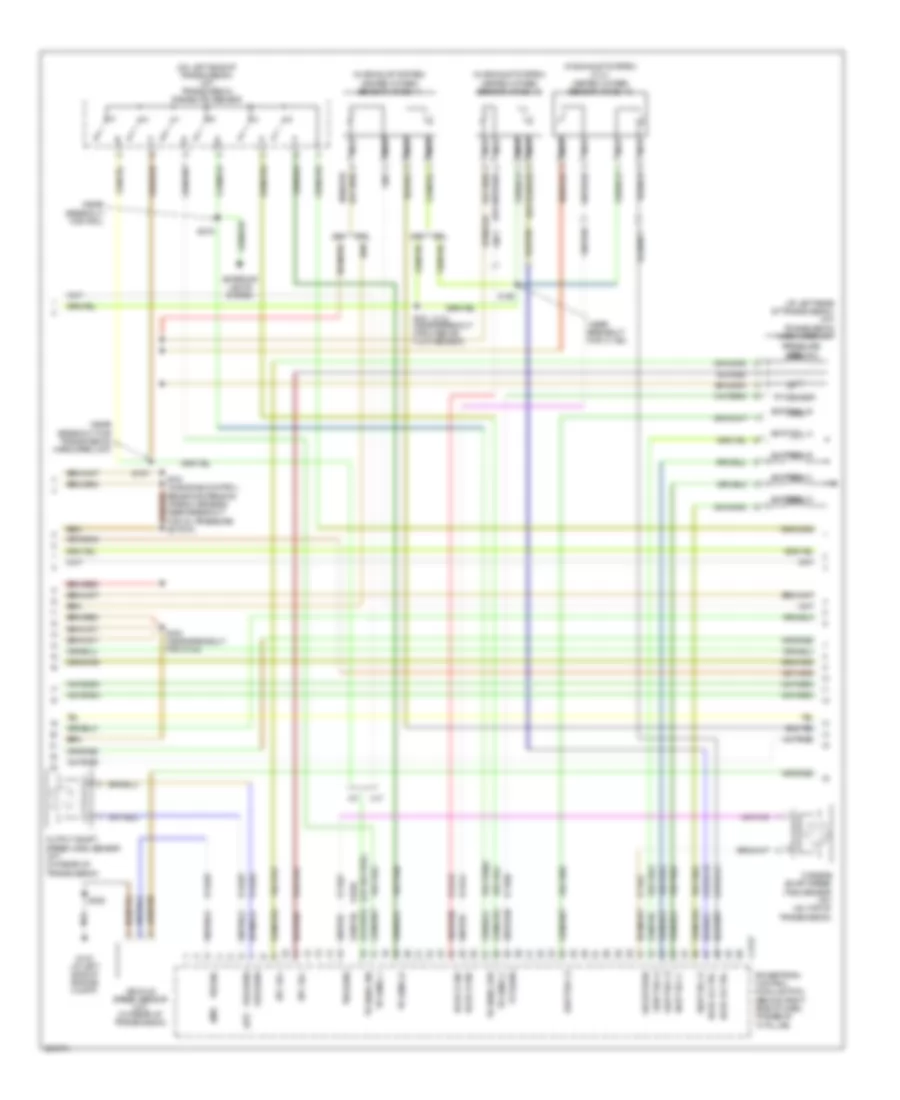
Engine Performance Wiring Diagram (3 of 4) for Ford Focus ZX3 S 2005
List of elements for Engine Performance Wiring Diagram (3 of 4) for Ford Focus ZX3 S 2005:
- (2.3l)
- (a/t)
- (at left rear of transmission) (a/t) transmission hardware unit
- (in exhaust system) (2.3l) heated oxygen sensor (ho2s) 13
- (in exhaust system) heated oxygen sensor (ho2s) 11
- (in exhaust system) heated oxygen sensor (ho2s) 12
- (m/t)
- (near breakout for c1168)
- (near breakout for pcm)
- (near breakout for transmission hardware unit)
- (on left side of transmission) (a/t) transmission range (tr) sensor
- (or 15s-ta37)
- 15s-ta17
- 15s-ta23
- 15s-ta24
- 15s-ta38a
- 15s-ta40
- 15s-ta41
- 15s-ta42
- 15s-ta63
- 15s-ta64
- 15s-ta65
- 2.0l
- 2.3l
- 8-bb6
- 8-rj15
- 8-rj29
- 8-rj41
- 8-ta27
- 8-ta36
- 9-rj29
- 9-ta27
- 91s-rj15
- 91s-rj41
- 91s-ta17
- A/t
- C175t
- Epc sol
- Exterior lights system
- G103 (at left side of engine compt)
- Ho2s 12 ctrl
- Ho2s 12 sig
- Ho2s 13 ctrl
- Ho2s 13 sig
- M/t
- Nca
- Oss sens
- Output shaft speed (oss) sensor (a/t) (on rear of transmission)
- Powertrain control module (pcm) (behind right side of dash, at base of "a" pillar)
- Pressure ctrl sol
- S161 (near breakout for mass air flow sensor)
- S163 (near breakout for c144)
- S187
- S190
- S191 (in engine control sensor extension wiring harness, near breakout for oil pressure switch)
- S252
- S275
- Shift sol a
- Shift sol b
- Shift sol c
- Shift sol d
- Shift sol e
- Sig return
- Tft sens
- Tft sensor
- Tr sens, 1
- Tr sens, 2
- Tr sens, d
- Tr sens, p/n
- Tr sens, rev
- Tss sens
- Turbine shaft speed (tss) sensor (a/t) (on top of transmission)
- Vehicle speed sensor (m/t) (on rear of transmission)
- Vss sig
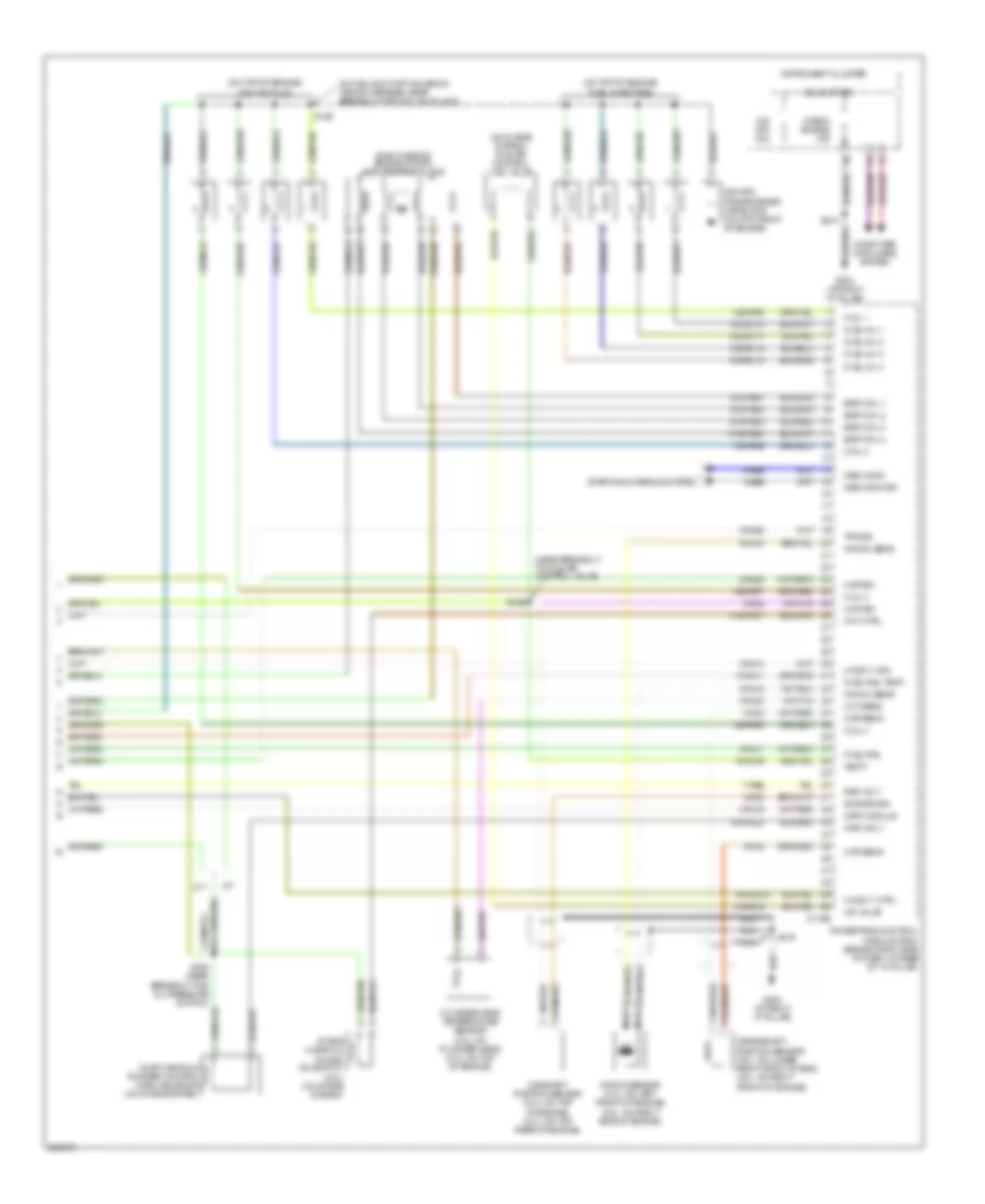
Engine Performance Wiring Diagram (4 of 4) for Ford Focus ZX3 S 2005
List of elements for Engine Performance Wiring Diagram (4 of 4) for Ford Focus ZX3 S 2005:
- (in fuel shut-off solenoid wiring harness, near breakout for coil on plug 2)
- (near breakout to idle air control valve)
- (on intake system) idle air control (iac) valve
- (on top of engine) coil on plug
- (on top of engine) fuel injectors
- (right side of engine compt) egr stepper motor
- 10-rj11
- 15-rl9a
- 15s-rr5
- 15s-rr6
- 15s-rr7
- 15s-rr8
- 31s-pa37
- 31s-rl10
- 31s-rl11
- 31s-rl12
- 31s-rl13
- 31s-rl20
- 31s-rl9
- 4-eb6
- 5-eb6
- 7-re8
- 8-rj11
- 8-rj14
- 8-rj16
- 8-rj18
- 8-rj20
- 8-rj28
- 8-rj3
- 8-rj33
- 8-rj4
- 9-rj18
- 9-rj3
- 9-rj4
- 91s-pa51
- 91s-pa52
- 91s-pa53
- 91s-pa54
- 91s-rj14
- A/t
- C175e
- Camshaft position sensor (2.0l: on top of engine) (2.3l: on top rear of engine)
- Check engine ind
- Cht sens
- Ckp sens
- Cmp sig
- Coil 1
- Coil 2
- Coil 3
- Coil 4
- Computer data lines system
- Crankshaft position sensor (2.0l: on lower right front of eng) (2.3l: on right front of engine)
- Cylinder-head temperature sensor (2.0l: on cylinder head) (2.3l: on top of engine)
- Egr coil 1
- Egr coil 2
- Egr coil 3
- Egr coil 4
- Fuel inj 1
- Fuel inj 2
- Fuel inj 3
- Fuel inj 4
- Fuel rail
- Fuel rail temp
- G202 (at right "a" pillar)
- G203 (at right "a" pillar)
- Gen comm
- Gen monitor
- Ho2s 11 ctrl
- Ho2s 11 sig
- Iac valve
- Ignition transformer capacitor (on top front of engine)
- Imrc module
- Imrc sol 1
- Imtv ctrl
- Inlet manifold runner control (imrc) solenoid (on intake system)
- Instrument cluster
- Intake manifold tuning valve (imtv) (2.3l) (on intake system)
- Knock sens
- Knock sensor (2.0l: on left front of engine) (2.3l: on right side of engine)
- M/t
- Map sig
- Nca
- O/d off ind
- Powertrain control module (pcm) (behind right side of dash, at base of "a" pillar)
- Ref volt
- S156 (near breakout for oil pressure switch)
- S169
- S199
- S212
- S278
- Sig return
- Solid state
- Starting/charging system
- Tps sig
- Vbatt