ENGINE PERFORMANCE
2.5L
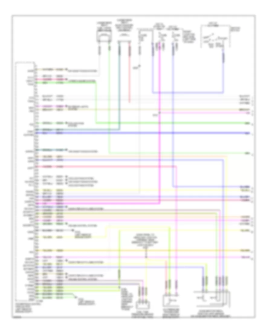
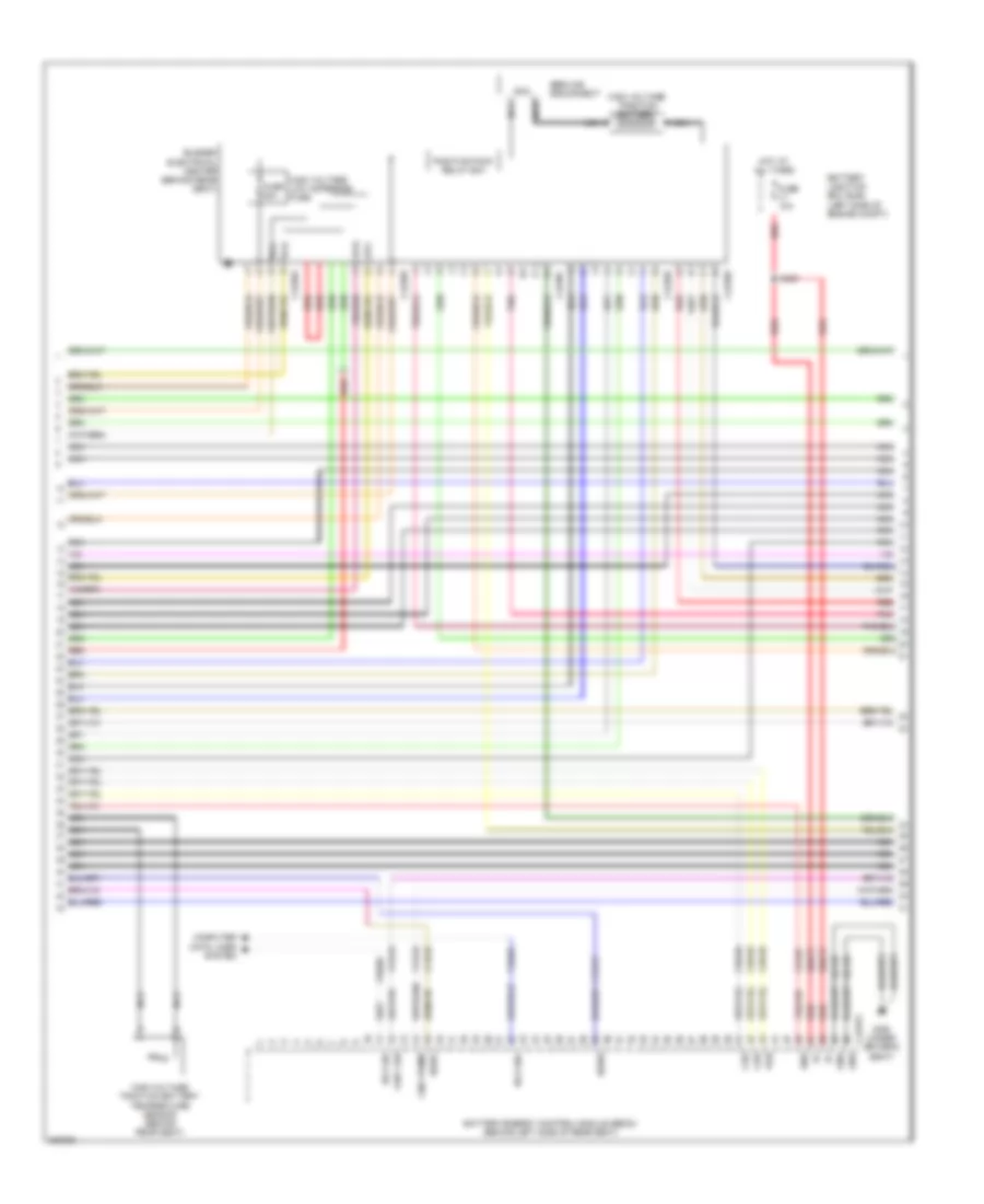
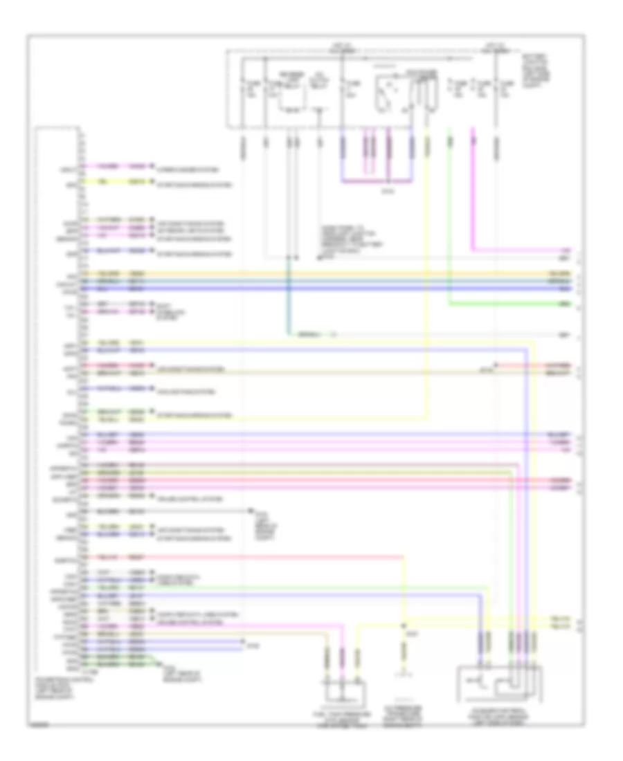
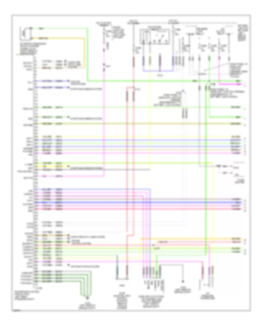
2.5L, Engine Performance Wiring Diagram, Except Hybrid (1 of 5) for Ford Fusion S 2010

List of elements for 2.5L, Engine Performance Wiring Diagram, Except Hybrid (1 of 5) for Ford Fusion S 2010:
- 10a
- 15a
- 40a
- A/c cycling pressure transducer
- Accelerator pedal position (app) sensor (left side of dash)
- Accr
- Acpt
- Air conditioning system
- App1
- App1rtn
- App1vref
- App2
- App2rtn
- App2vref
- Battery junction box (bjb) (left side of engine compt)
- Bpp
- Bps
- C175b
- Canv
- Case gnd
- Cbb46
- Cbk01
- Cbk02
- Cbp44
- Ccb08
- Cdb08
- Cdc10
- Cdc12
- Cdc15
- Cdc35
- Ce114
- Ce302
- Ce336
- Ces09
- Cet42
- Cet43
- Ch302
- Computer data lines system
- Cooling fans system
- Cruise control system
- Exterior lights system
- Fcv
- Feps
- Floor shifter
- Fpc
- Fpm
- Ftpt
- Ftptref
- Fuel tank pressure (ftp) sensor (top of fuel tank)
- Fuse
- G102 (left rear of engine compt)
- Gd120
- Gencom
- Genmon
- Hot at all times
- Hs can+
- Hs can-
- Iat
- Ign
- Kapwr
- Le136
- Le137
- Le230
- Le424
- Maf
- Mafrtn
- Pcm power relay
- Pcmrc
- Power gnd
- Powertrain control module (pcm) (left rear of engine compt)
- Re136
- Re137
- Re325
- Re407
- Res08
- S119
- S125
- S143
- Sbb23
- Sccs
- Sccsrtn
- Shift interlock system
- Sigrtnc
- Smc
- Smcs
- Smr
- Starting/charging system
- Tip +
- Tip -
- Vce03
- Vdb04
- Vdb05
- Ve225
- Ve518
- Ve701
- Ve702
- Ve740
- Ve808
- Ve922
- Ves10
- Vh433
- Vmc05
- Vpwr
- Vpwrtr-pn
- Vref
- Vsout
- Wiper/washer system
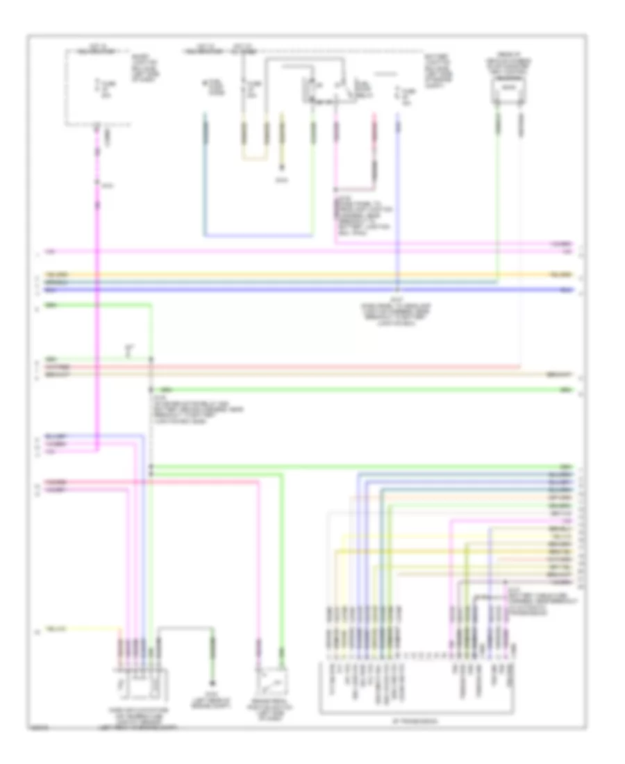
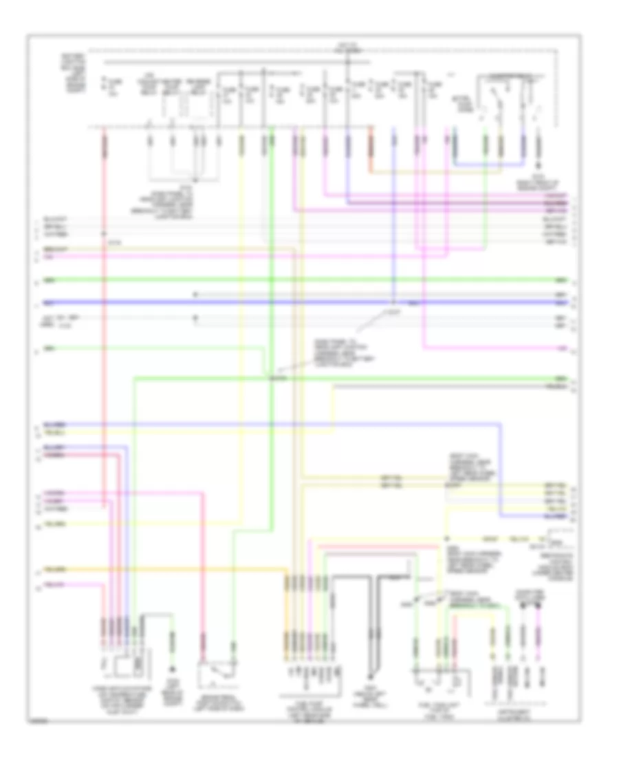
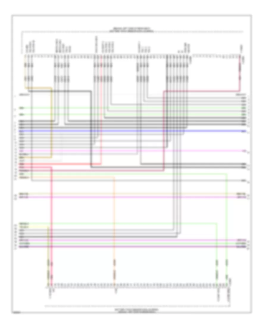
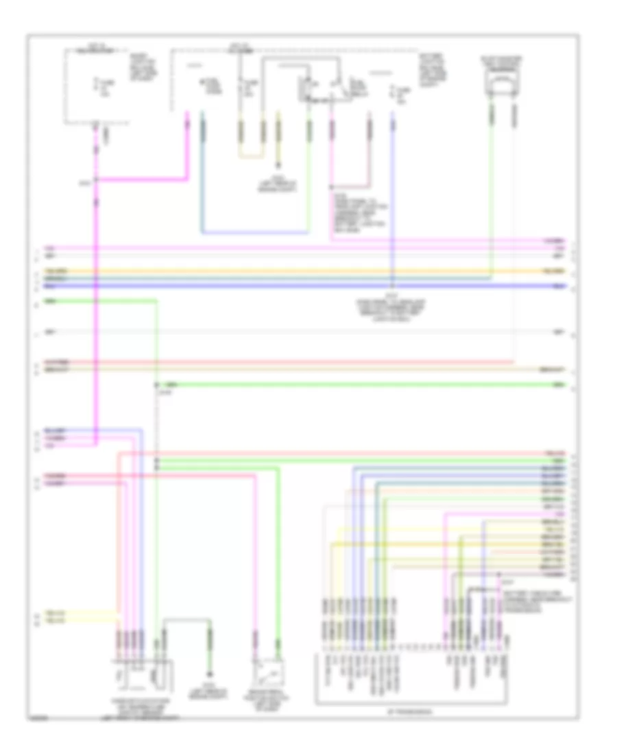
2.5L, Engine Performance Wiring Diagram, Except Hybrid (2 of 5) for Ford Fusion S 2010
List of elements for 2.5L, Engine Performance Wiring Diagram, Except Hybrid (2 of 5) for Ford Fusion S 2010:
- (rear of vehicle chassis) evap canister vent control solenoid
- 15a
- 30a
- 6f transmission
- Battery junction box (bjb) (left side of engine compt)
- Brake pedal position switch (left side of dash)
- C168a
- C168b
- C2280e
- Cblr/c456 vfs
- Cet05
- Cet06
- Cet07
- Cet08
- Cet09
- Cet10
- Cet18
- Cet25
- Fuel pump diode
- Fuel pump relay
- Fuse
- G102 (left rear of engine compt)
- G103
- Hot at all times
- Hot in run or start
- Le111
- Lpc vfs
- M/t
- Mass air flow/intake air temperature (maf/iat) sensor (left front of engine compt)
- Oss
- Re406
- Ret24
- S121
- S137 (dash panel to headlamp junction harness, near breakout to battery junction box)
- S140 (starter motor relay and battery ground harness, near breakout to battery junction box (bjb))
- S146
- S147 (battery cable wire harness, near breakout to automatic transmission)
- Smart junction box (sjb) (left side of dash)
- Sol pwr
- Ssa cb1234 vfs
- Ssb c35r vfs
- Ssc cb26 vfs
- Sse on/off sol
- Tcc vfs
- Tft
- Tft sig rtn
- Trs
- Trs/oss gnd
- Trs/oss pwr
- Tss
- Tss gnd
- Tss pwr
- Vet26
- Vet27
- Vet32
- Vet33
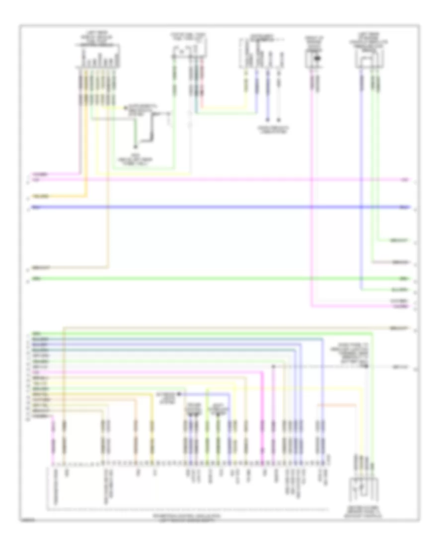
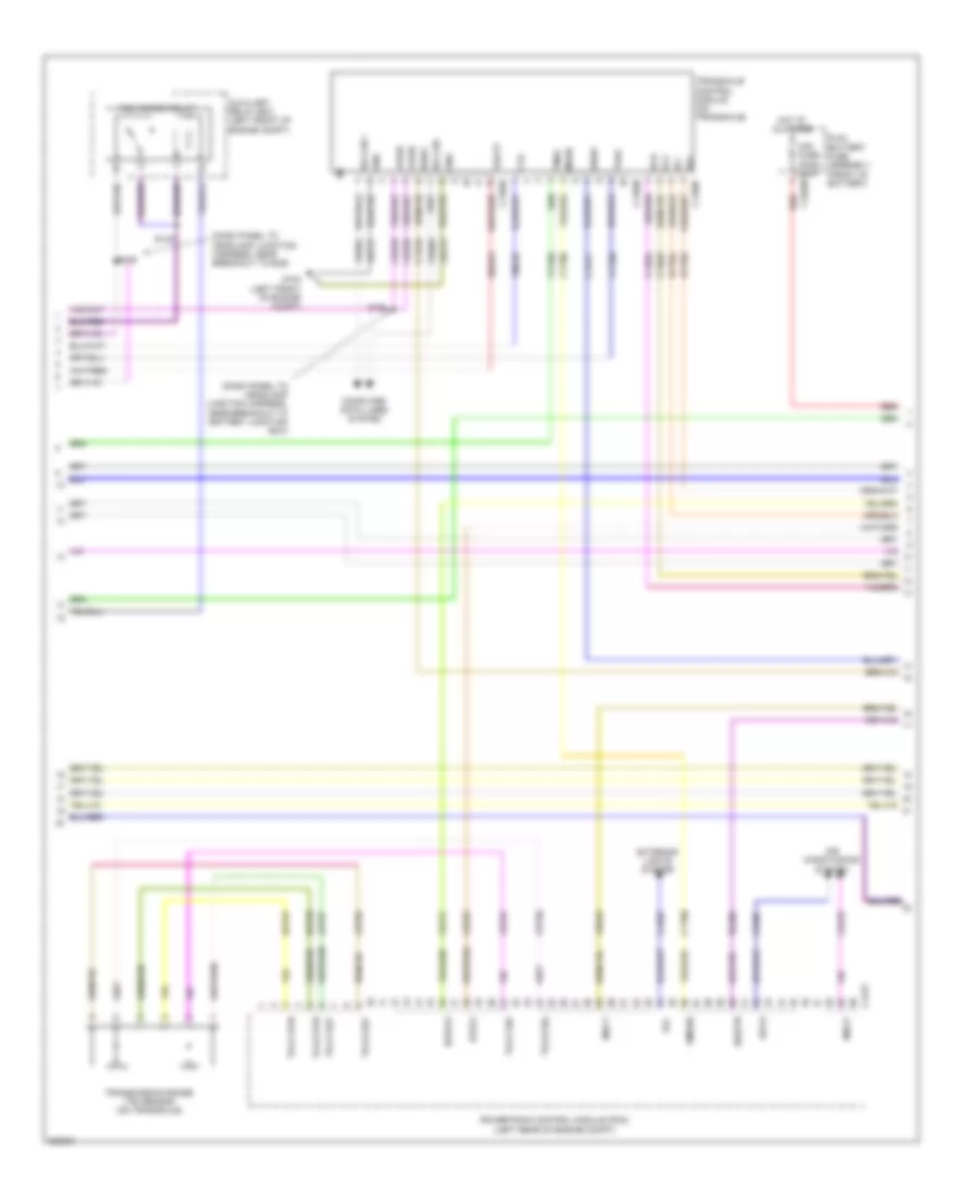
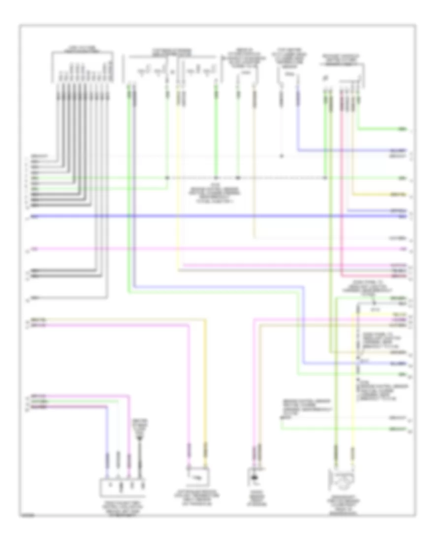
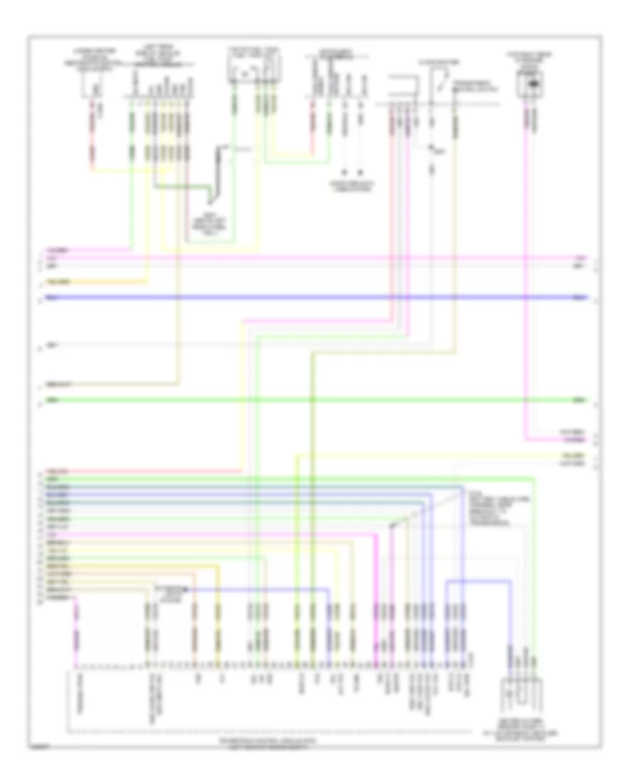
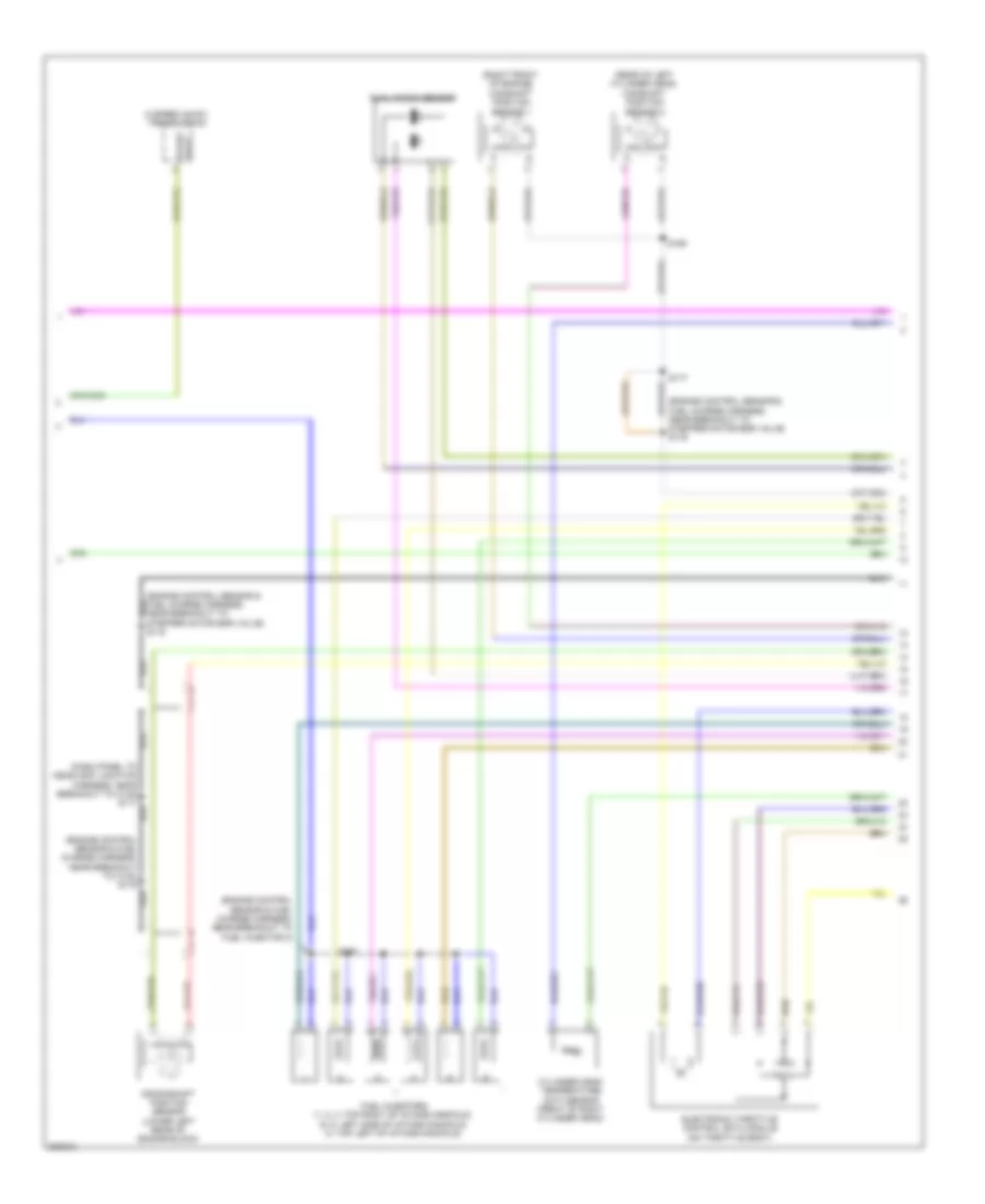
2.5L, Engine Performance Wiring Diagram, Except Hybrid (3 of 5) for Ford Fusion S 2010
List of elements for 2.5L, Engine Performance Wiring Diagram, Except Hybrid (3 of 5) for Ford Fusion S 2010:
- (dash panel to headlamp junction harness, near breakout to battery box) s182
- (front of engine) knock sensor
- (left rear of engine) manifold absolute pressure (map) sensor
- (left rear side of vehicle) fuel pump control module
- (top of fuel tank) fuel tank unit
- C175t
- Ce226
- Ce233
- Ce515
- Ce608
- Ce903
- Ce904
- Cet05
- Cet06
- Cet07
- Cet08
- Cet09
- Cet10
- Cet18
- Cet25
- Cet34
- Cls28
- Computer data lines system
- Cpp-bt
- Cpp-tt
- Cr167
- Cruise control system
- Ens
- Exterior lights system
- Fpc
- Fpm
- Fppwr
- Fprtn
- Fuel sender return
- Fuel sender signal
- G403 (above left rear wheel well)
- Gd151
- Gnd
- Heated oxygen sensor (ho2s) 12 (exhaust manifold)
- Ho2s-12
- Hs can+
- Hs can-
- Htr-12
- Ifs input
- Instrument cluster (ic)
- Lcp vfs
- Le111
- Oss
- Powertrain control module (pcm) (left rear of engine compt)
- Re226
- Re406
- Ret24
- Rlc
- Rmc32
- Shift interlock system
- Sigrtn
- Sol pwr
- Ssa cb1234 vfs
- Ssb c35r vfs
- Ssc cb26 vfs
- Ssd cblr/c456 vfs
- Sse on/off sol
- Tcc vfs
- Tcs
- Tft
- Tr gnd
- Trs
- Trs/oss/tss vpwr
- Tss
- Ve225
- Ve518
- Ve731
- Ve806
- Vet26
- Vet27
- Vet32
- Vet33
- Vmc11
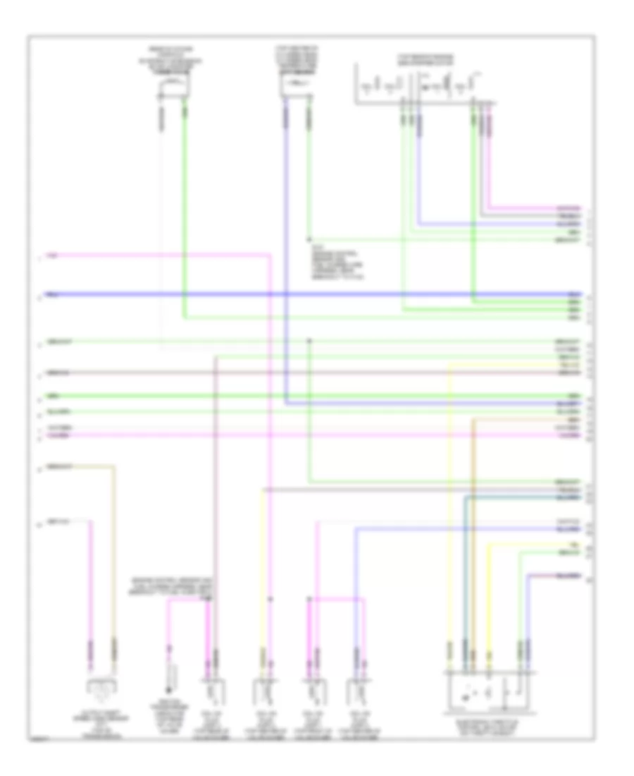
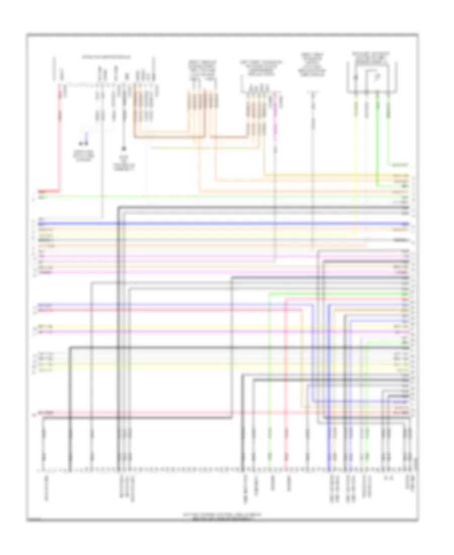
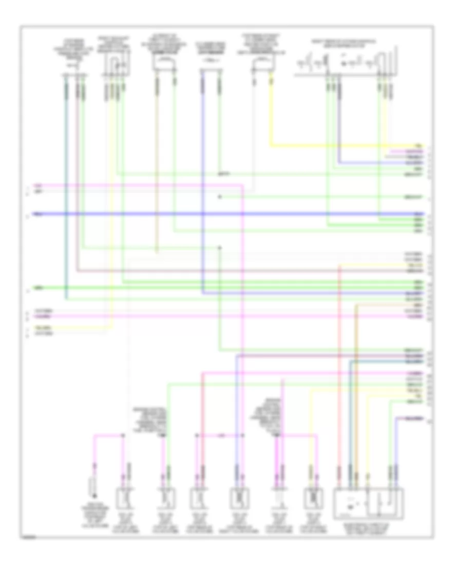
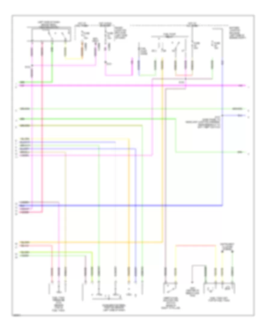
2.5L, Engine Performance Wiring Diagram, Except Hybrid (4 of 5) for Ford Fusion S 2010
List of elements for 2.5L, Engine Performance Wiring Diagram, Except Hybrid (4 of 5) for Ford Fusion S 2010:
- (engine control sensor and fuel charge harness, near breakout to fuel injector 2) s135
- (rear of intake manifold) evaporative emission (evap) canister purge valve
- (top center of cylinder head) cylinder head temperature (cht) sensor
- (top rear of engine) egr stepper motor
- Coil
- Coil on plug (cop) 1 (top front of valve cover)
- Coil on plug (cop) 2 (top center of valve cover)
- Coil on plug (cop) 3 (top center of valve cover)
- Coil on plug (cop) 4 (top rear of valve cover)
- Electronic throttle control (etc) motor (on throttle body)
- Ignition transformer capacitor (top rear of valve cover)
- Output shaft speed (oss) sensor (m/t) (top of transmission)
- S181 (engine control sensor and fuel charge wire harness, near breakout to c133)
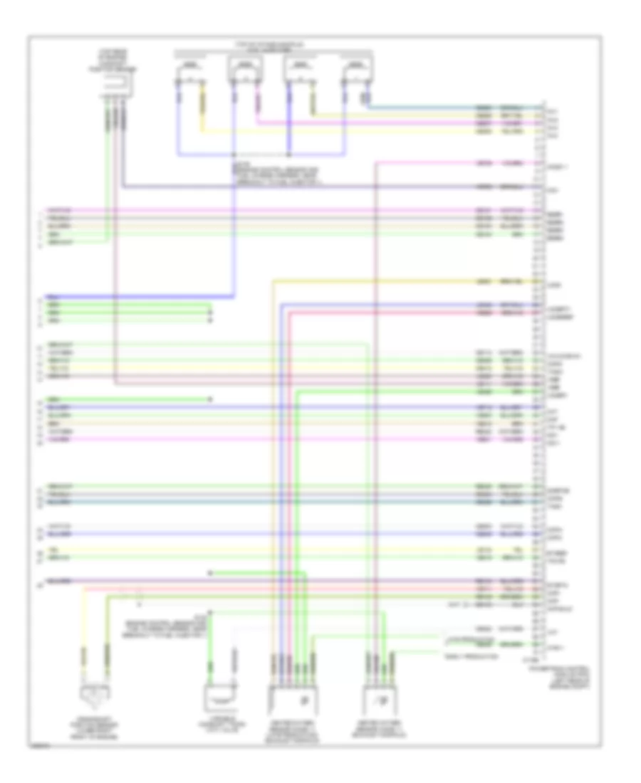
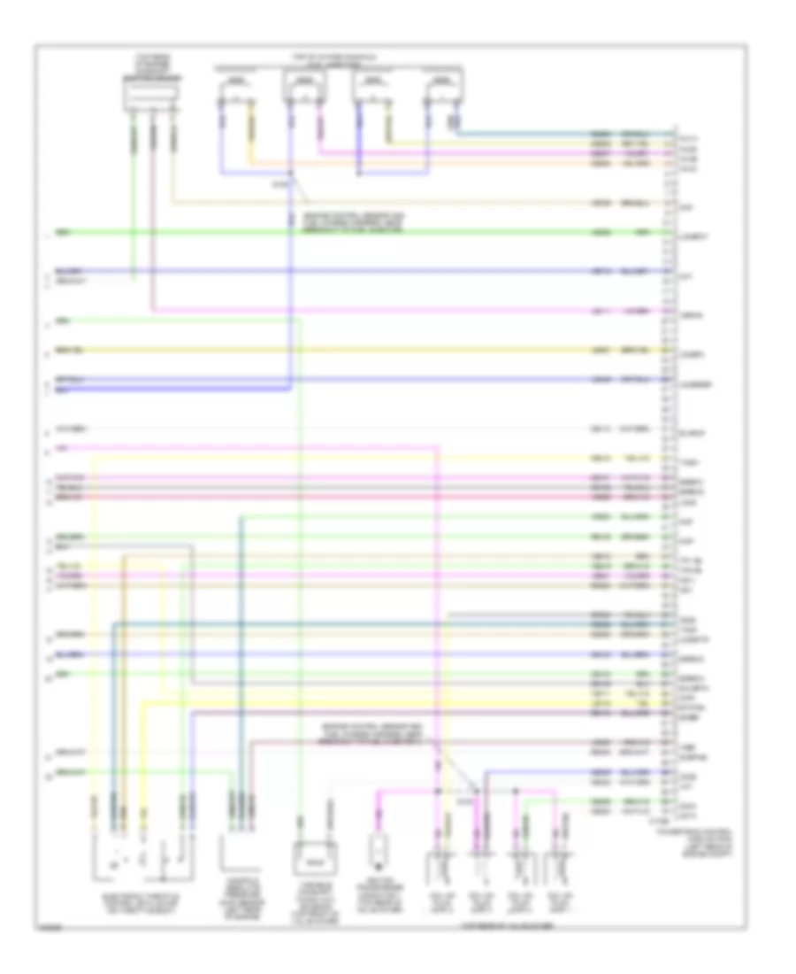
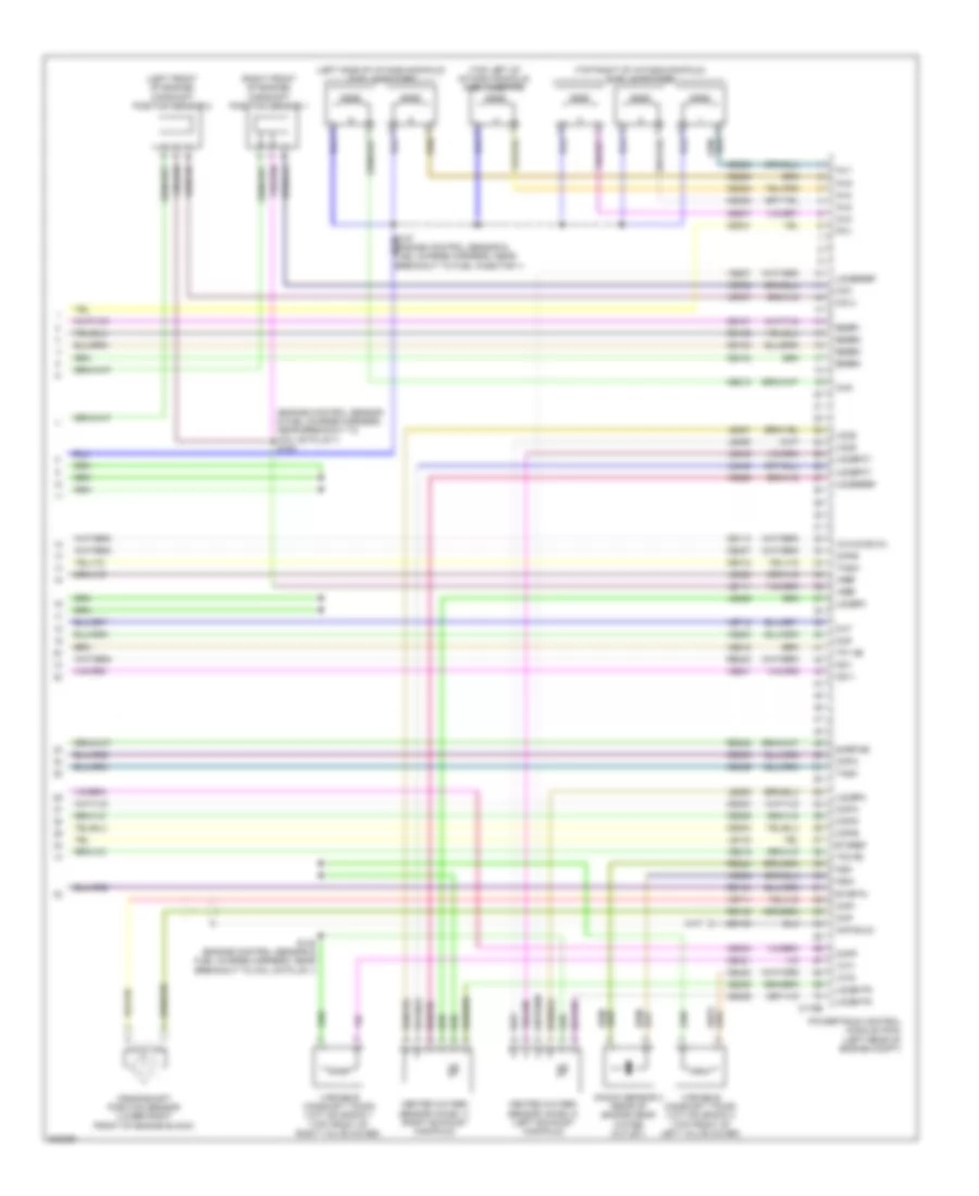
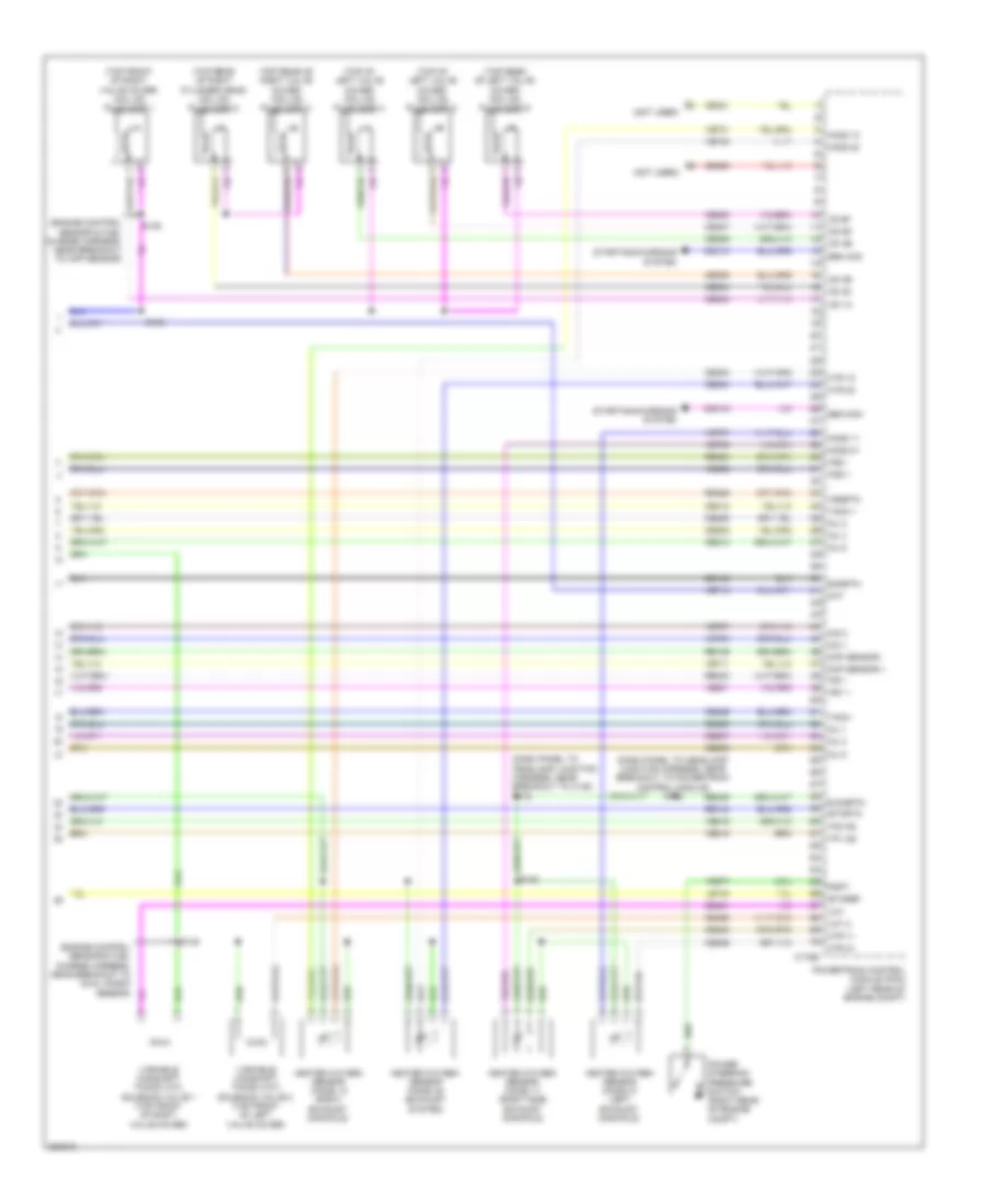
2.5L, Engine Performance Wiring Diagram, Except Hybrid (5 of 5) for Ford Fusion S 2010
List of elements for 2.5L, Engine Performance Wiring Diagram, Except Hybrid (5 of 5) for Ford Fusion S 2010:
- (engine control sensor and fuel charge harness, near breakout to fuel injector 1)
- (top of intake manifold) fuel injectors
- (top rear of engine) camshaft position sensor
- C175e
- Ce101
- Ce102
- Ce103
- Ce104
- Ce113
- Ce205
- Ce206
- Ce207
- Ce208
- Ce235
- Ce303
- Ce304
- Ce305
- Ce306
- Ce412
- Ce422
- Ce426
- Cht
- Cid1
- Ckp shld
- Ckp+
- Ckp-
- Cop-a
- Cop-b
- Cop-c
- Cop-d
- Crankshaft position sensor (lower right front of engine)
- De135
- Early production
- Eegr1
- Eegr2
- Eegr3
- Eegr4
- Etcref
- Etcrtn
- Heated oxygen sensor (ho2s) 11 (exhaust manifold)
- Heated oxygen sensor (ho2s) 11 (late production) (exhaust manifold)
- Ho2s-11
- Htr-11
- Inj1
- Inj2
- Inj3
- Inj4
- Ks1+
- Ks1-
- Late production
- Le111
- Le134
- Le423
- Le448
- Le451
- Le452
- Map
- Powertrain control module (pcm) (left rear of engine compt)
- Re134
- Re135
- Re323
- Re405
- S138 (engine control sensor and fuel charge harness, near breakout to fuel injector 1)
- Sigrtne
- Tacm+
- Tacm-
- Tp1 ns
- Tp2 ps
- Uo2s
- Uo2sgref
- Uo2spc
- Uo2spct
- Variable camshaft timing (vct) valve
- Vct
- Ve706
- Ve711
- Ve712
- Ve735
- Ve801
- Ve803
- Ve818
- Ve819
- Ve826
- Vmv-cc/evmv
- Vref
2.5L, Engine Performance Wiring Diagram, Hybrid (1 of 8) for Ford Fusion S 2010
List of elements for 2.5L, Engine Performance Wiring Diagram, Hybrid (1 of 8) for Ford Fusion S 2010:
- (dash panel to headlamp junction harness, near breakout to battery junction box) s157
- (under rear seat) evap canister vent control solenoid
- (under rear seat) fuel vapor vent valve
- A/c pressure transducer (right rear of engine compt)
- Accelerator pedal position (app) sensor (on accelerator pedal bracket)
- Accr
- Aclpcs
- Acpsw
- Acpt
- Air conditioning system
- App1
- App2
- Boo
- Bps
- C175b
- C2280b
- C2280d
- C2280e
- Canv
- Cbb40
- Cbk01
- Cbp28
- Cbp44
- Ccb08
- Cdb08
- Ce114
- Ce302
- Ce420
- Cec01
- Cec02
- Cec03
- Ces09
- Cgnd
- Ch302
- Ch421
- Ch425
- Computer data lines system
- Cooling fans system
- Cruise control system
- Cto
- Ectref2
- Ectrtn2
- Etcref1
- Etcrtn1
- Exterior lights system
- Fc v
- Fc1
- Fc2
- Feps
- Fpc
- Fpm
- Ftp
- Ftpref
- Fuel tank pressure sensor (top of fuel tank)
- Fuse 10a
- Fuse 15a
- Fuse 5a
- Fvvv
- G102 (left rear of engine compt)
- Gd120
- Gnd
- Hot at all times
- Hot in start or run
- Hs can+
- Hs can-
- Iat
- Ignition switch
- Injpwrm
- Isp-r
- Isp-r/s
- Kapwr
- Le136
- Le137
- Le230
- Le424
- Lock
- Maf
- Mafrtn
- Off
- Pcmrc
- Powertrain control module (pcm) (left rear of engine compt)
- Re136
- Re137
- Re325
- Re407
- Res08
- Run/ run/ acc
- S121
- S195 (dash panel to headlamp junction harness, near breakout to bjb)
- S230
- Sbb23
- Sccs
- Sccsrtn
- Sigrtn
- Smart junction box (sjb) (left side of dash)
- Start
- Tgac
- Tmac
- Vdb04
- Vdb05
- Ve225
- Ve518
- Ve701
- Ve702
- Ve740
- Ve808
- Ve922
- Ves10
- Vh433
- Vmc02
- Vmc05
- Vpwr
- Vref
- Vsout
- Vyt05
- Vyt06
- Wiper/washer system
2.5L, Engine Performance Wiring Diagram, Hybrid (2 of 8) for Ford Fusion S 2010
List of elements for 2.5L, Engine Performance Wiring Diagram, Hybrid (2 of 8) for Ford Fusion S 2010:
- (body main harness, near breakout to g401)
- (body main harness, near breakout to left rear wheel speed sensor) s461
- (dash panel to headlamp junction harness, near breakout to battery junction box)
- (not used) c133
- 10a
- 15a
- 20a
- 30a
- 40a
- Battery junction box (bjb) (left side of engine compt)
- Brake pedal position switch (left side of dash)
- C310a
- Cbb48
- Ce226
- Computer data lines system
- Cr167
- Ens
- Fpc
- Fpm
- Fppwr
- Fprtn
- Fuel pump control module (left rear side of vehicle)
- Fuel pump diode
- Fuel sender return
- Fuel sender signal
- Fuel tank unit (top of fuel tank)
- Fuse
- G102 (left rear of engine compt)
- G104 (right front of engine compt)
- G403 (above left rear wheel well)
- Gd151
- Gnd
- Heater pump relay
- Hot at all times
- Ifs vpwr
- Injector relay
- Instrument cluster (ic)
- M/e coolant pump relay
- Mass air flow/intake air temperature (maf/iat) sensor (on air cleaner inlet duct)
- Ms can+
- Ms can-
- Nca
- Re226
- Restraints control module (rcm) (under center console)
- Reverse lamp relay
- S119
- S137
- S140
- S144 (dash panel to headlamp junction harness, near breakout to battery junction box)
- S462
- S463
- S464 (body main harness, near breakout to left rear wheel speed sensor)
- Ve225
- Ve518
2.5L, Engine Performance Wiring Diagram, Hybrid (3 of 8) for Ford Fusion S 2010
List of elements for 2.5L, Engine Performance Wiring Diagram, Hybrid (3 of 8) for Ford Fusion S 2010:
- (dash panel to headlamp junction harness, near breakout to battery junction box)
- (dash panel to headlamp junction harness, near breakout to bjb)
- Air conditioning system
- Auxiliary relay box (left front of engine compt)
- C1458a
- C1458b
- C1458c
- C175t
- Cbb39
- Ce233
- Ce318
- Ch307
- Cls28
- Computer data lines system
- Cto
- Cyb03
- Cyb04
- Cyb16
- Cyb17
- Cyt08
- Dual battery fuse assembly (front of battery)
- Exterior lights system
- G103 (left front of engine compt)
- Gd121
- Gmsdn
- Gnd
- Ho2s12
- Hot at all times
- Hpcr
- Hs can +
- Hs can -
- Htr12
- Hv+
- Hv-
- Hvi+
- Hyi-
- Hyt03
- Hyt04
- Isdn1
- Let56
- Let57
- Mecp
- Mect
- Midi fuse (pink) 200a c1620b
- Msdn
- Pcm power relay
- Powertrain control module (pcm) (left rear of engine compt)
- Re406
- Red
- Ret56
- Ret57
- Rlc
- S143
- S193
- S194
- Sbb23
- Sigrtn
- Tgac
- Tmac
- Tr-a1 ref
- Tr-a1 rtn
- Tr-a1 sig
- Tr-a2 ref
- Tr-a2 rtn
- Tr-a2 sig
- Transaxle control module (on transaxle)
- Transmission range (tr) sensor (on transaxle)
- Vbatt
- Vdb04
- Vdb05
- Ve731
- Ve810
- Vet56
- Vet57
- Vmc02
- Vpwr
- Vyt05
- Vyt06
2.5L, Engine Performance Wiring Diagram, Hybrid (4 of 8) for Ford Fusion S 2010
List of elements for 2.5L, Engine Performance Wiring Diagram, Hybrid (4 of 8) for Ford Fusion S 2010:
- (exhaust manifold) heated oxygen sensor (ho2s) 12
- (left front of engine) air conditioning compressor module (accm)
- (on transaxle assembly)
- (right rear of engine compt) anti-lock brake system (abs) module
- (right rear of engine compt) high voltage junction box
- Battery energy control module (becm) (behind left side of rear seat)
- Becm in+
- Becm in-
- C1457a
- C1457b
- C1457c
- C1457d
- C1469a
- C1469b
- C4237b
- Cbk03
- Ch401
- Computer data lines system
- Cont crl posh
- Cont crl posl
- Cyb03
- Cyd01
- Cyd02
- Dc/dc converter module
- Fvi+
- Fvi-
- G105
- Gd108
- Gnd
- Hs can+
- Hs can-
- Hv+
- Hv-
- Hvdc+
- Hvdc-
- Hvi+
- Hvi-
- Hyt03
- Hyt04
- Instr can h
- Instr can l
- J1-a39
- J1-a41
- J1-a44
- J1-a47
- J1-a55
- J1-a56
- J1-a58
- J1-a59
- J1-a61
- J1-a62
- J1a02
- J1a07
- J1a11
- J1a16
- J1a17
- J1a18
- J1a51
- J1a65
- J1a66
- J1a69
- J1a70
- Nca
- Pack hs can l
- Pack hs canl
- Prech ctlh
- Prech ctll
- Pwr gnd
- Red
- Sdc02
- Sig rtn
- Temp inlet
- Temp inlet rtn
- Vbatt
- Vdb04
- Vdb05
- Vpwr
2.5L, Engine Performance Wiring Diagram, Hybrid (5 of 8) for Ford Fusion S 2010
List of elements for 2.5L, Engine Performance Wiring Diagram, Hybrid (5 of 8) for Ford Fusion S 2010:
- 100a
- Battery energy control module (becm) (behind left side of rear seat)
- Battery junction box (bjb) (left side of engine compt)
- Bussed electrical center (behind rear seat)
- C4236a
- C4236b
- C4236c
- C4236d
- C4236e
- C4237a
- Cbb48
- Computer data lines system
- Cr167
- Crs
- Cyb16
- Cyb17
- Ens
- Fan1 fbb
- Fan1 pwmb
- Fuse 10a
- Fuse 40a
- G300 (under driver's seat)
- Gd126
- Gnd
- High voltage low amperage fuse
- High voltage traction battery
- High voltage traction battery temperature sensor (behind rear seat)
- Hot at all times
- Hs can+
- Hs can-
- Hvi+
- Hvi-
- Isdn1
- Isdn2
- Nca
- Pnk
- Positive pack relay 60a
- Psr
- Red
- S460
- Sbb17
- Service disconnect
- Vdb04
- Vdb05
- Vyb18
- Vyb19
2.5L, Engine Performance Wiring Diagram, Hybrid (6 of 8) for Ford Fusion S 2010
List of elements for 2.5L, Engine Performance Wiring Diagram, Hybrid (6 of 8) for Ford Fusion S 2010:
- (behind left side of rear seat) battery pack sensor module (bpsm)
- Battery pack sensor module (bpsm) (behind left side of rear seat)
- C4238a
- C4238b
- Cs aout 1
- Cs aout 2
- Cs gnd
- Cs vref
- Instr can h
- Instr can l
- J1a02
- J1a07
- J1a16
- J1a17
- J1a18
- J1a51
- J1a65
- J1a66
- J1a69
- J1a70
- J2a
- J2a16
- J2a36
- J2a67
- J2a70
- J2b1
- J2b12
- J2b13
- J2b14
- J2b2
- J2b24
- J2b25
- J2b26
- J2b27
- J2b3
- J2b35
- J2b36
- J2b37
- J2b38
- Jqa11
- Ldl
- Nca
- Pack hs can h
- Pnk
- Pwr gnd
- Red
- Sig rtn
- Tsl 1
- Tsl 2
- Tsl 3
- Tsl 9
- Tsl rtn 1
- Tsl rtn 10
- Tsl rtn 2
- Tsl rtn 3
- Tsl rtn 9
- Tsl10
- V cont pos
- V sd
2.5L, Engine Performance Wiring Diagram, Hybrid (7 of 8) for Ford Fusion S 2010
List of elements for 2.5L, Engine Performance Wiring Diagram, Hybrid (7 of 8) for Ford Fusion S 2010:
- (center of rear floor pan) g401
- (dash panel to headlamp junction harness, near breakout to c145)
- (dash panel to headlamp junction harness, near breakout to pcm)
- (engine control sensor and fuel charge harness, near breakout to c145) s180
- (exhaust manifold) heated oxygen sensor (ho2s) 11
- (rear of intake manifold) evaporative emission (evap) canister purge valve
- (top center of cylinder head) cylinder head temperature sensor
- (top rear of engine) egr stepper motor
- Coil
- Crankshaft position sensor (lower right front of engine block)
- Fbb
- Gnd
- High voltage traction battery
- Knock sensor (front of engine)
- Motor electronics coolant temperature (mect) sensor (on transaxle)
- Nca
- Pwmb
- S117
- S118
- S138 (engine control sensor and fuel charge harness, near breakout to fuel injector 1)
- S185 (engine control sensor and fuel charge harness, near breakout to c145)
- Traction battery control cooling fan (behind left side of rear seat)
- Tsl 1
- Tsl 2
- Tsl 3
- Tsl 9
- Tsl rtn 1
- Tsl rtn 10
- Tsl rtn 2
- Tsl rtn 3
- Tsl rtn 9
- Tsl10
2.5L, Engine Performance Wiring Diagram, Hybrid (8 of 8) for Ford Fusion S 2010
List of elements for 2.5L, Engine Performance Wiring Diagram, Hybrid (8 of 8) for Ford Fusion S 2010:
- (engine control sensor and fuel charge harness, near breakout to fuel injector 4)
- (engine control sensor and fuel charge harness, near breakout to fuel injector)
- (top of intake manifold) fuel injectors
- (top rear of engine) camshaft position sensor
- (top rear of valve cover)
- C175e
- Cd1a
- Cd2d
- Cd3b
- Cd4c
- Ce101
- Ce102
- Ce103
- Ce104
- Ce113
- Ce205
- Ce206
- Ce207
- Ce208
- Ce235
- Ce303
- Ce304
- Ce305
- Ce306
- Ce412
- Ce422
- Ce426
- Cht
- Ckp+
- Ckp-
- Cmp
- Coil on plug (cop) 1
- Coil on plug (cop) 2
- Coil on plug (cop) 3
- Coil on plug (cop) 4
- De135
- Ecref
- Egrmc1
- Egrmc2
- Egrmc3
- Egrmc4
- Electronic throttle control (etc) motor (on throttle body)
- Etctrn
- Evapcp
- Ignition transformer capacitor 1 (top rear of valve cover)
- Inj1a
- Inj2d
- Inj3b
- Inj4c
- Ks1+
- Ks1-
- Le111
- Le134
- Le423
- Le448
- Le451
- Le452
- Manifold absolute pressure (map) sensor (left rear of engine)
- Map
- Powertrain control module (pcm) (left rear of engine compt)
- Re134
- Re135
- Re323
- Re405
- S135
- S139
- Shldrtn
- Sigrtne
- Tacm+
- Tacm-
- Tp1 ns
- Tp2 ps
- Uo2s
- Uo2sgref
- Uo2shtr
- Uo2spc
- Uo2spct
- Variable camshaft timing (vct) solenoid (top front of valve cover)
- Vbpwr
- Vct
- Ve706
- Ve711
- Ve712
- Ve801
- Ve803
- Ve818
- Ve819
- Ve826
- Vref
3.0L
3.0L, Engine Performance Wiring Diagram (1 of 5) for Ford Fusion S 2010
List of elements for 3.0L, Engine Performance Wiring Diagram (1 of 5) for Ford Fusion S 2010:
- (dash panel to headlamp junction harness, near breakout to battery junction box) s144
- 10a
- 15a
- 40a
- A/c clutch relay
- A/c pressure transducer (right rear of engine compt)
- Accelerator pedal position (app) sensor (left side of dash)
- Accr
- Acpt
- Air conditioning system
- App1
- App1vref
- App2
- App2vref
- Appsrtn1
- Appsrtn2
- Battery junction box (bjb) (left side of engine compt)
- Bpp
- Bps
- C175b
- Can+
- Can-
- Canvnt
- Cbb46
- Cbk01
- Cbp44
- Ccb08
- Cdb08
- Cdc10
- Cdc12
- Cdc15
- Cdc35
- Ce114
- Ce302
- Ce336
- Ces09
- Cet42
- Cet43
- Ch302
- Computer data lines system
- Cooling fans system
- Cruise control system
- Exterior lights system
- Fcv
- Feps
- Fpc
- Fpm
- Ftpt
- Ftptref
- Fuel tank pressure (ftp) sensor (top of fuel tank)
- Fuse
- G102 (left rear of engine compt)
- Gd120
- Gencom
- Genmon
- Gnd
- Hot at all times
- Iat
- Ign
- Kapwr
- Le136
- Le137
- Le230
- Le424
- Maf
- Mafrtn
- Pcm power relay
- Pcmrc
- Powertrain control module (pcm) (left rear of engine compt)
- Re136
- Re137
- Re325
- Re407
- Res08
- Reverse lamp relay
- S119
- S125
- S143
- S157
- Sbb23
- Sccs
- Sccsrtn
- Shift interlock system
- Sigrtnc
- Smc
- Smcs
- Smr
- Starting/charging system
- Tip +
- Tip -
- Vdb04
- Vdb05
- Ve225
- Ve518
- Ve701
- Ve702
- Ve740
- Ve808
- Ve922
- Vec03
- Ves10
- Vh433
- Vmc05
- Vpwr
- Vref
- Vsout
- Wiper/washer system
3.0L, Engine Performance Wiring Diagram (2 of 5) for Ford Fusion S 2010
List of elements for 3.0L, Engine Performance Wiring Diagram (2 of 5) for Ford Fusion S 2010:
- (battery cable wire harness, near breakout to automatic transmission)
- 10a
- 15a
- 30a
- 6f transmission
- Battery junction box (bjb) (left side of engine compt)
- Brake pedal position switch (left side of dash)
- C168a
- C168b
- C2280e
- Cblr/c456 vfs
- Cet05
- Cet06
- Cet07
- Cet08
- Cet09
- Cet10
- Cet18
- Cet25
- Evap canister vent control solenoid
- Fuel pump diode
- Fuel pump relay
- Fuse
- G102 (left rear of engine compt)
- G103 (left rear of engine compt)
- Hot at all times
- Hot in run or start
- Le111
- Lpc vfs
- Mass air flow/intake air temperature (maf/iat) sensor (left front of engine compt)
- Oss
- Re406
- Ret24
- S121
- S130 (dash panel to headlamp junction harness, near breakout to battery junction box (bjb))
- S137 (dash panel to headlamp junction harness, near breakout to battery junction box)
- S140
- S146
- S147
- Smart junction box (sjb) (left side of dash)
- Sol pwr
- Ssa cb1234 vfs
- Ssb c35r vfs
- Ssc cb26 vfs
- Sse on/off sol
- Tcc vfs
- Tft
- Tft sig rtn
- Trs
- Trs/oss gnd
- Trs/oss pwr
- Tss
- Tss gnd
- Tss pwr
- Vet26
- Vet27
- Vet32
- Vet33
3.0L, Engine Performance Wiring Diagram (3 of 5) for Ford Fusion S 2010
List of elements for 3.0L, Engine Performance Wiring Diagram (3 of 5) for Ford Fusion S 2010:
- (left rear side of vehicle) fuel pump control module
- (top of fuel tank) fuel tank unit
- (top right rear of engine) knock sensor 1
- (under center console) restraints control module (rcm)
- C175t
- C310a
- Ce226
- Ce233
- Ce234
- Ce608
- Cet05
- Cet06
- Cet07
- Cet08
- Cet09
- Cet10
- Cet18
- Cet25
- Cet34
- Cet42
- Cet43
- Cls28
- Computer data lines system
- Cr167
- Ens
- Exterior lights system
- Floor shifter
- Fpc
- Fpm
- Fppwr
- Fprtn
- Fuel sender return
- Fuel sender signal
- G403 (above left rear wheel well)
- Gd151
- Gnd
- Heated oxygen sensor (ho2s) 13 (w/ low emission vehicles) (exhaust system)
- Ho2s-12
- Ho2s-13
- Hs can+
- Hs can-
- Htr-12
- Htr-13
- Ifs input
- Instrument cluster (ic)
- Lcp vfs
- Le111
- Nca
- Oss
- Powertrain control module (pcm) (left rear of engine compt)
- Re226
- Re406
- Ret24
- Rlc
- S148 (battery cable wire harness, near breakout to automatic transmission)
- S251
- Sigrtn
- Sol pwr
- Ssa cb1234 vfs
- Ssb c35r vfs
- Ssc cb26 vfs
- Ssd cblr/c456 vfs
- Sse on/off sol
- Tcc vfs
- Tcs
- Tft
- Tip+
- Tip-
- Tr gnd
- Transmission control switch
- Trs
- Trs/oss/ vpwr
- Tss
- Ve225
- Ve518
- Ve731
- Ve733
- Vet26
- Vet27
- Vet32
- Vet33
3.0L, Engine Performance Wiring Diagram (4 of 5) for Ford Fusion S 2010
List of elements for 3.0L, Engine Performance Wiring Diagram (4 of 5) for Ford Fusion S 2010:
- (engine control sensor and fuel charge harness, near breakout to coil on plug 3) s135
- (engine control sensor and fuel charge harness, near breakout to fuel injector 4) s136
- (in front of throttle body) evaporative emission (evap) canister purge valve
- (right exhaust manifold) heated oxygen sensor (ho2s) 12
- (right rear of intake manifold) egr stepper motor
- (top rear of engine) manifold absolute pressure (map) sensor
- (top rear of right cylinder head) heated positive crankcase ventilation (pcv) valve
- Coil
- Coil on plug (cop) 1 (top front of valve cover)
- Coil on plug (cop) 2 (top of right valve cover)
- Coil on plug (cop) 3 (top rear of right valve cover)
- Coil on plug (cop) 4 (top of left valve cover)
- Coil on plug (cop) 5 (top of left valve cover)
- Coil on plug (cop) 6 (top rear of valve cover)
- Cylinder head temperature (cht) sensor
- Electronic throttle control (etc) motor (on throttle body)
- Ignition transformer capacitor (top front of left valve cover)
- S181
3.0L, Engine Performance Wiring Diagram (5 of 5) for Ford Fusion S 2010
List of elements for 3.0L, Engine Performance Wiring Diagram (5 of 5) for Ford Fusion S 2010:
- (engine control sensor & fuel charge harness, near breakout to coil on plug 1) s153
- (left front of engine) camshaft position sensor 2
- (left side of intake manifold) fuel injectors
- (right front of engine) camshaft position sensor 1
- (top left of intake manifold) fuel injector
- (top right of intake manifold) fuel injectors
- C175e
- Ce101
- Ce102
- Ce103
- Ce104
- Ce113
- Ce205
- Ce206
- Ce207
- Ce208
- Ce209
- Ce210
- Ce235
- Ce236
- Ce303
- Ce304
- Ce305
- Ce306
- Ce307
- Ce308
- Ce321
- Ce412
- Ce421
- Ce422
- Ce426
- Cht
- Cid 2
- Cid1
- Ckp shld
- Ckp+
- Ckp-
- Cop-a
- Cop-b
- Cop-c
- Cop-d
- Cop-e
- Cop-f
- Crankshaft position sensor (lower right front of engine block)
- De135
- Eegr1
- Eegr2
- Eegr3
- Eegr4
- Etcref
- Etcrtn
- Heated oxygen sensor (ho2s) 11 (right exhaust manifold)
- Heated oxygen sensor (ho2s) 21 (left exhaust manifold)
- Inj1
- Inj2
- Inj3
- Inj4
- Inj5
- Inj6
- Knock sensor 2 (rear of engine near water outlet)
- Ks1+
- Ks1-
- Ks2+
- Ks2-
- Le111
- Le134
- Le423
- Le448
- Le449
- Le450
- Le451
- Le452
- Le453
- Map
- Pcv
- Powertrain control module (pcm) (left rear of engine compt)
- Re134
- Re135
- Re323
- Re324
- Re405
- S138 (engine control sensor & fuel charge harness, near breakout to coil on plug 1)
- Sigrtne
- Tacm+
- Tacm-
- Tp1 ns
- Tp2 ps
- Uo2s
- Uo2sgref
- Uo2shtr
- Uo2spc
- Uo2spct
- Variable camshaft timing (vct) solenoid 1 (top front of right valve cover)
- Variable camshaft timing (vct) solenoid 2 (top front of left valve cover)
- Vct1
- Vct2
- Ve706
- Ve707
- Ve711
- Ve712
- Ve801
- Ve802
- Ve803
- Ve818
- Ve819
- Ve826
- Ve827
- Vmv-cc/evmv
- Vref
3.5L
3.5L, Engine Performance Wiring Diagram (1 of 4) for Ford Fusion S 2010
List of elements for 3.5L, Engine Performance Wiring Diagram (1 of 4) for Ford Fusion S 2010:
- (dash panel to headlamp junction harness, near breakout to battery junction box)
- (dash panel to headlamp junction harness, near breakout to g103)
- A/c clutch relay
- A/c pressure transducer
- Accr
- Acpt
- Air conditioning system
- App 1
- App 2
- App 3
- App1ref
- App1rtn
- App2ref
- App2rtn
- Battery junction box (bjb) (left side of engine compt)
- Bpp
- Bps
- C sigrtn
- C vref
- C175b
- C2280e
- Canvnt
- Case gnd
- Cbk01
- Cbp44
- Cbp46
- Ccb08
- Cdb08
- Cdc12
- Cdc35
- Ce114
- Ce132
- Ce302
- Ce336
- Ce608
- Ces09
- Cet40
- Ch302
- Computer data lines system
- Cooling fans system
- Cruise control system
- Evap canister vent control solenoid (rear of vehicle chassis)
- Evaporative emission (evap) canister purge valve (right rear of engine compt)
- Evmv
- Fc v
- Feps
- Floor shifter
- Fpc
- Fpm
- Ftpt
- Ftptref
- Fuse 10a
- Fuse 15a
- Fuse 20a
- Fuse 40a
- G102 (left rear of engine compt)
- Gd120
- Hot at all times
- Hot in start or run
- Hs can +
- Hs can -
- Iat
- Ignition
- Injpwrm
- Kapwr
- Le136
- Le137
- Le230
- Le424
- Maf
- Mafrtn
- Mass air flow/intake air temperature (maf/iat) sensor (left side of engine compt)
- O/d
- Pcm control
- Pcm power relay
- Powertrain control module (pcm) (left rear of engine compt)
- Pwr
- Pwr gnd
- Pwr gnd 1
- Pwr gnd 2
- Pwr gnd 3
- Re136
- Re137
- Re325
- Re407
- Res08
- Reverse lamp relay
- S119
- S121
- S125 (dash panel to headlamp junction harness, near breakout to battery junction box)
- S140
- S143
- S144
- S179
- S251
- Sbb23
- Sccs
- Sccsrtn
- Sdc
- Smart junction box (sjb) (left side of dash)
- Smc
- Smr
- Starting/charging system
- Trsw pn
- Vdb04
- Vdb05
- Ve225
- Ve701
- Ve702
- Ve703
- Ve740
- Ve808
- Ve922
- Vec03
- Ves10
- Vh433
- Vpwr
3.5L, Engine Performance Wiring Diagram (2 of 4) for Ford Fusion S 2010
List of elements for 3.5L, Engine Performance Wiring Diagram (2 of 4) for Ford Fusion S 2010:
- (left side of dash) brake pedal position switch
- Accelerator pedal position sensor (left side of dash)
- Battery junction box (bjb) (left side of engine compt)
- Boo input c2280b
- C2280a
- C2280d
- Fuel pump diode
- Fuel pump relay
- Fuel tank pressure (ftp) sensor (top of fuel tank)
- Fuel tank unit (top of fuel tank)
- Fuse 10a
- Fuse 15a
- Fuse 30a
- G401 (center of rear floor pan)
- Hot at all times
- Hot in run or start
- Inertia fuel shutoff (ifs) switch (base of right "a" pillar)
- Instrument cluster system
- S121
- S130
- S137 (dash panel to headlamp junction harness, near breakout to anti theft switch)
- Smart junction box (sjb) (left side of dash)
3.5L, Engine Performance Wiring Diagram (3 of 4) for Ford Fusion S 2010
List of elements for 3.5L, Engine Performance Wiring Diagram (3 of 4) for Ford Fusion S 2010:
- (dash panel to headlamp junction harness, near breakout to c145) s117
- (engine control sensor & fuel charge harness, near breakout to c133) s178
- (engine control sensor & fuel charge harness, near breakout to fuel injector 3)
- (engine control sensor & fuel charge harness, near breakout to stepper motor egr valve) s176
- (rear of left cylinder head) camshaft position sensor 2
- (right front of engine) camshaft position sensor 1
- 6 speed an-f21 transmission
- Crankshaft position sensor (lower left rear of engine block)
- Cylinder head temperature (cht) sensor (front of right cylinder head)
- Dual knock sensor
- Electronic throttle control (etc) module (on throttle body)
- Fuel injectors (1, 2, 3: top right of intake manifold) (5, 6: left side of intake manifold) (4: top left of intake manifold)
- Lock start
- S159
- S160
- S177
3.5L, Engine Performance Wiring Diagram (4 of 4) for Ford Fusion S 2010
List of elements for 3.5L, Engine Performance Wiring Diagram (4 of 4) for Ford Fusion S 2010:
- (dash panel to headlamp junction harness, near breakout to c145) s116
- (dash panel to headlamp junction harness, near breakout to powertrain control module) s102
- (engine control sensor & fuel charge harness, near breakout to ckp sensor)
- (engine control sensor & fuel charge harness, near breakout to dual knock sensor)
- (not used)
- (top front of right valve cover) coil on plug (cop) 1
- (top of left valve cover) coil on plug (cop) 4
- (top of left valve cover) coil on plug (cop) 5
- (top rear of left valve cover) coil on plug (cop) 6
- (top rear of right cylinder head) coil on plug (cop) 2
- (top rear of right valve cover) coil on plug (cop) 3
- C175e
- Cd 1a
- Cd 2c
- Cd 3e
- Cd 4b
- Cd 5d
- Cd 6f
- Cdc10
- Cdc15
- Ce205
- Ce206
- Ce207
- Ce208
- Ce209
- Ce210
- Ce233
- Ce234
- Ce235
- Ce236
- Ce303
- Ce304
- Ce305
- Ce306
- Ce307
- Ce308
- Ce321
- Ce328
- Ce412
- Ce421
- Ce422
- Ce426
- Cht
- Cid 1
- Cid 2
- Ckp sensor +
- Ckp sensor -
- De135
- E sigrtn
- Etcref
- Etcrtn
- Gen com
- Gen mon
- Heated oxygen sensor (ho2s) 11 (right side exhaust manifold)
- Heated oxygen sensor (ho2s) 12 (right exhaust manifold)
- Heated oxygen sensor (ho2s) 21 (left exhaust manifold)
- Heated oxygen sensor (ho2s) 22 (exhaust system)
- Ho2s 11
- Ho2s 12
- Ho2s 21
- Ho2s 22
- Htr 11
- Htr 12
- Htr 21
- Htr 22
- Inj 1
- Inj 2
- Inj 3
- Inj 4
- Inj 5
- Inj 6
- Ks1 +
- Ks1 -
- Ks2 +
- Ks2 -
- Le134
- Power steering pressure switch (right rear of engine compt)
- Powertrain control module (pcm) (left rear of engine compt)
- Pspt
- Re134
- Re135
- Re323
- Re324
- Re405
- Re429
- S135
- S136
- S138
- Shdrtn
- Starting/charging system
- Tacm +
- Tacm -
- Tp1 ns
- Tp2 ps
- Variable camshaft timing (vct) solenoid valve 1 (top front of right valve cover)
- Variable camshaft timing (vct) solenoid valve 2 (top front of left valve cover)
- Vct
- Vct 2
- Ve706
- Ve707
- Ve711
- Ve712
- Ve731
- Ve733
- Ve735
- Ve737
- Ve801
- Ve802
- Ve818
- Ve819
- Vrsrtn