ENGINE PERFORMANCE
4.0L
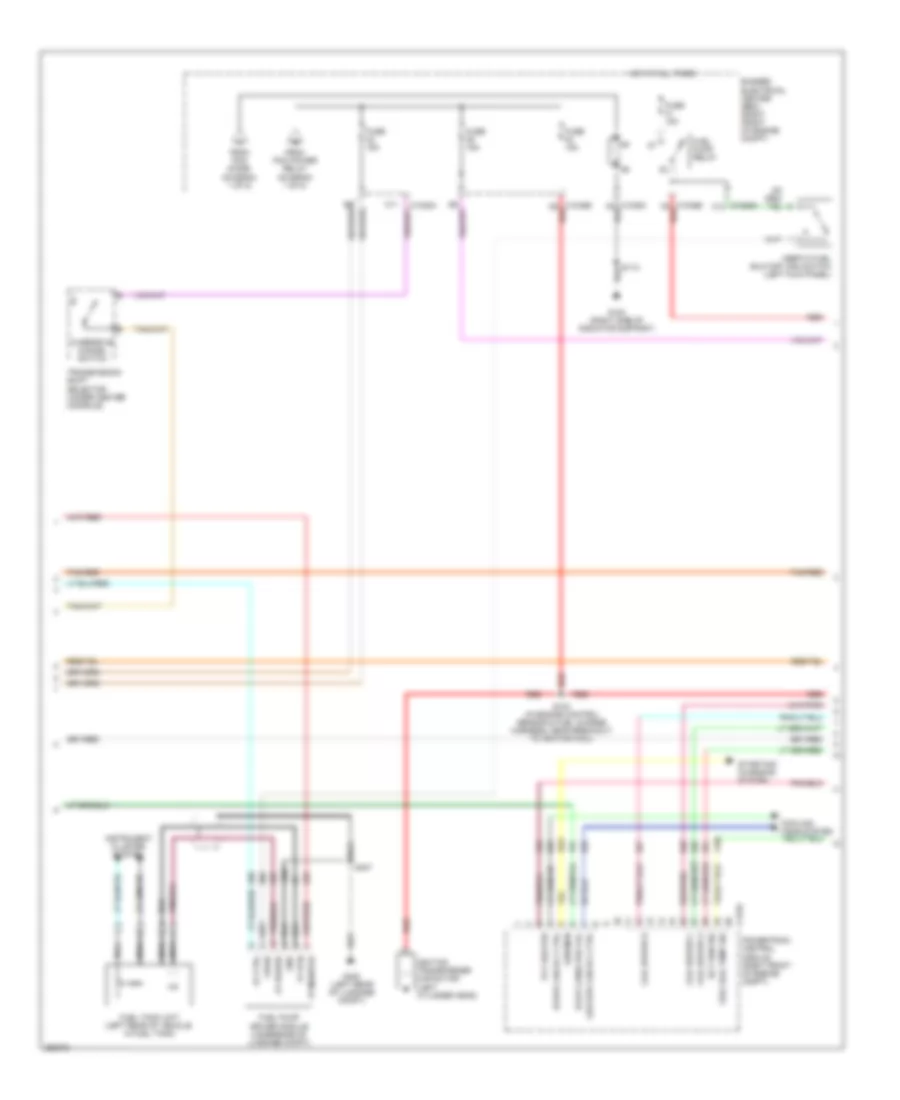
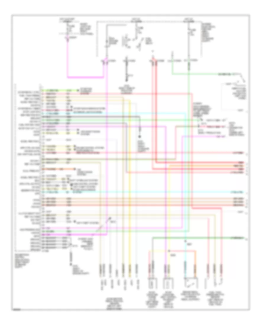
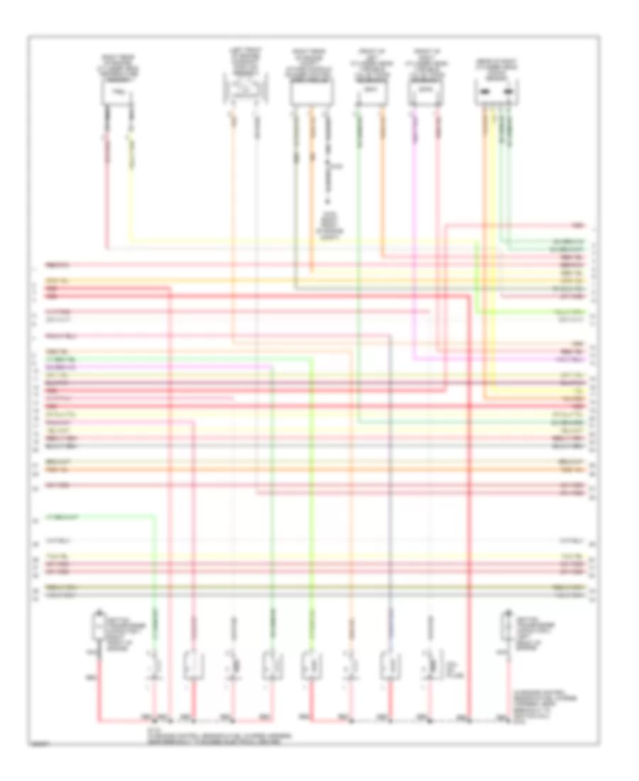
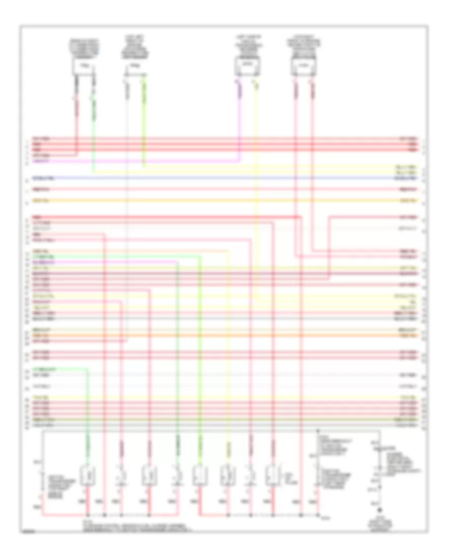
4.0L, Engine Performance Wiring Diagram (1 of 5) for Ford Mustang 2007

List of elements for 4.0L, Engine Performance Wiring Diagram (1 of 5) for Ford Mustang 2007:
- (late production) (early production)
- (late production: near breakout to g204) (early production: near breakout to left front wheel speed sensor) s213 s113
- (near breakout to c211) s212
- 57o
- Accel ped pos 2
- Accel ped pos 3
- Accelerator pedal position sensor (below left side of dash)
- Accr
- Accs
- Acp
- Air bag mntr
- Air conditioning system
- Anti- theft system
- Anti-theft system
- App1
- App2
- App3
- Brake pedal position switch (on brake pedal support)
- Brk ped pos sw
- Brk ped sw
- Bussed electrical center (bec) (right front of engine compt)
- C175b
- Canister vent sol
- Cpp
- Cruise control system
- Data link connector (dlc) (under left side of dash)
- Deactivator switch (on clutch pedal support)
- Drv pmp fuel mntr
- Etcref1
- Etcref2
- Etcrtn
- Evap canister purge valve (left rear of engine compt)
- Evap canister vent control solenoid (left rear of vehicle)
- Exterior lights system
- Fuel pmp drv mod
- Fuel tank press
- Fuel tank pressure (ftp) sensor (left rear of vehicle, on fuel tank)
- Fuse 10a
- Fuse 15a
- Fuse 5a
- G102 (right front of engine compt)
- G103 (right front of engine compt)
- G204 (left kick panel)
- Generator com
- Ground
- Hot at all times
- Hot in run or start
- Hs can +
- Hs can -
- Isp-r
- Kapwr
- Mod program sig
- Od cancel sw sig
- Pcm diode
- Pcm power relay
- Pcm rc
- Power steering pressure switch (left side of engine compt)
- Powertrain control module (right front of engine compt)
- Pwr steering sw
- Red/pnk
- Ref voltage
- Rx sig
- S115
- S214 s114 (late production: near breakout to left front channel subwoofer amplifier) (early production: near breakout to left front wheel speed sensor)
- S215
- S225
- S227
- Sig rtn
- Sigrtn
- Smart junction box (sjb) (right kick panel)
- Spd ctrl sw rtn
- Spd ctrl sw sig
- Starter rly ctrl
- Starter rly feed
- Starting/ charging system
- Starting/charging system
- Sw sig
- Tan/red
- To fuel pump relay (diagram 2 of 5)
- To fuse 42 15a (diagram 2 of 5)
- Tx sig
- Vpwr
- Vref a
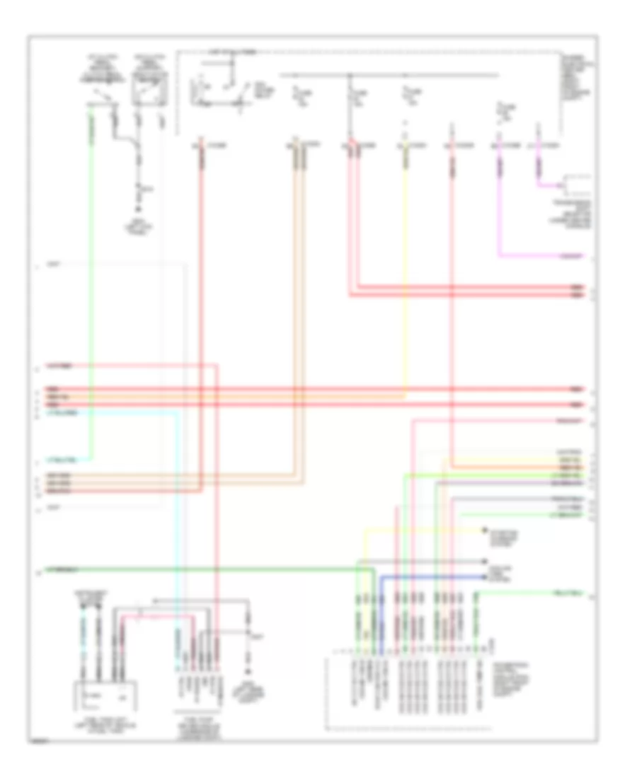
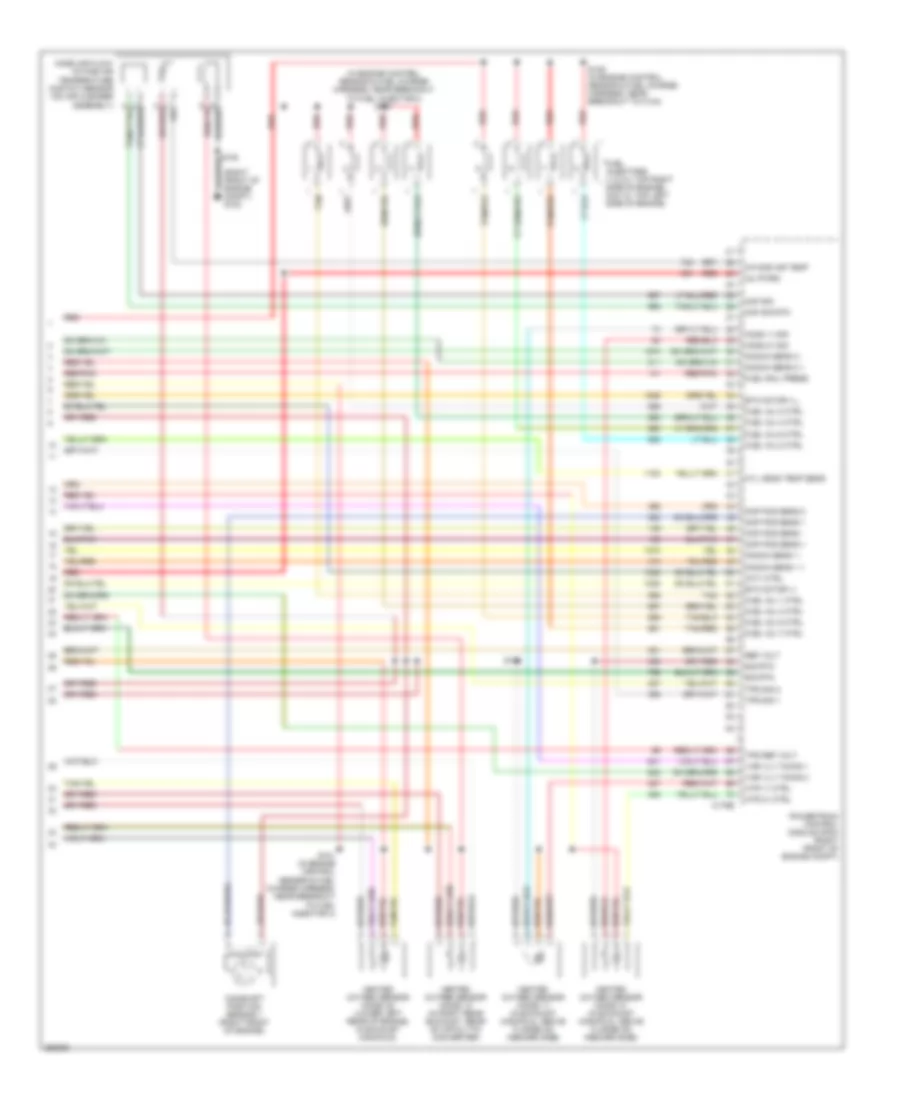
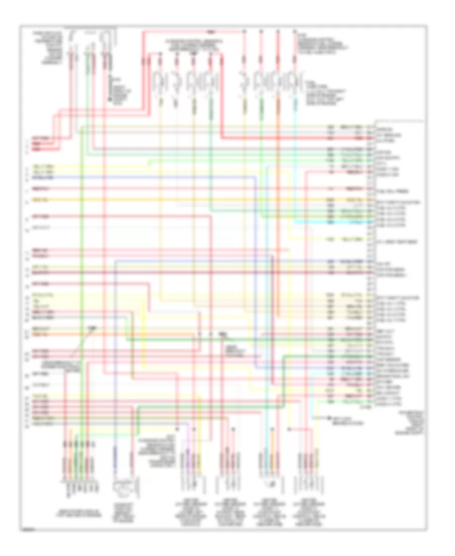
4.0L, Engine Performance Wiring Diagram (2 of 5) for Ford Mustang 2007
List of elements for 4.0L, Engine Performance Wiring Diagram (2 of 5) for Ford Mustang 2007:
- Bussed electrical center (bec) (right front of engine compt)
- C1035a c12
- C1035b d5 red
- C1035b f6 red
- C11
- C175e
- Coil driver a
- Coil driver b
- Coil driver c
- Cooling fans system
- Ect sen sig
- Evap canis pur val
- Fp ctrl
- Fp monitor
- Fp power
- Fp rtn
- From pcm diode (diagram 1 of 5)
- From pcm power relay (diagram 1 of 5)
- Fuel pump driver module (underside of luggage compt)
- Fuel pump relay
- Fuel rail temp sig
- Fuel tank unit (left rear of vehicle, in fuel tank)
- Fuse 15a
- G100 (right side of radiator support)
- G400 (left rear of luggage compt)
- Gen mon
- Gnd
- Hi spd fan rly ctrl
- Hot at all times
- Ignition transformer capacitor (left cylinder head)
- Inertia fuel shutoff (ifs) switch (left kick panel)
- Instrument cluster system
- Low spd fan rly ctrl
- Nca
- Overdrive cancel switch
- Pcv heater
- Powertrain control module (right front of engine compt)
- Red
- S104 (in engine control sensor & fuel charge harness, near breakout to ignition coil)
- S407
- Starting/ charging system
- Tan/red
- Transmission shift selector (under center console)
- Vpwr
4.0L, Engine Performance Wiring Diagram (3 of 5) for Ford Mustang 2007
List of elements for 4.0L, Engine Performance Wiring Diagram (3 of 5) for Ford Mustang 2007:
- (center front of engine, below right side of water pump) crankshaft position sensor
- (left front of engine compt) a/c pressure transducer sensor
- (left rear side of transmission) output shaft speed (oss) sensor
- (on throttle body assembly)
- (on top of engine) s103
- (right front of engine compt) g102
- (top front of engine)
- (top left side of transmission) intermediate shaft speed (iss) sensor
- (top left side of transmission) turbine shaft speed (tss) sensor
- (top rear of engine) ignition coil
- Electronic throttle control (etc) motor (on throttle body)
- Engine coolant temperature (ect) sensor
- Fuel rail pressure & temperature sensor (top rear of engine)
- Heated positive crankcase ventilation (pcv) valve (top right front of engine)
- Knock sensor (top of engine)
- Nca
- Pressure sn
- Red
- Red/pnk
- Sig rtn
- Spark plugs
- Tan/red
- Temp sn
- Throttle position (tp) sensor
- Vref
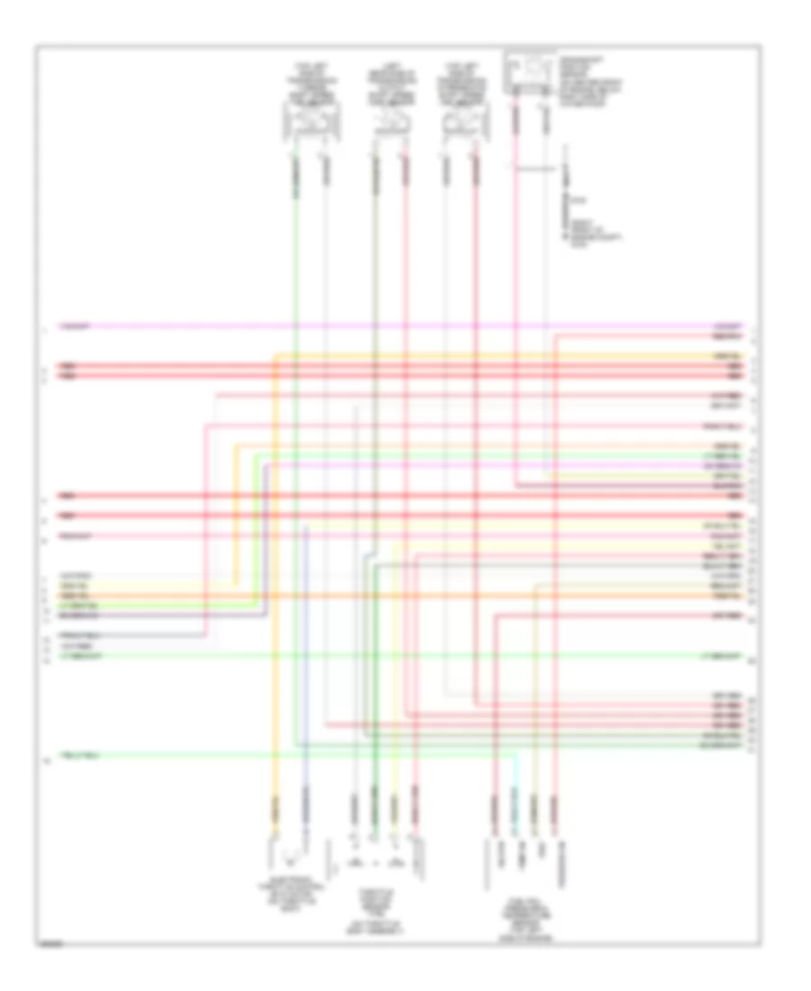
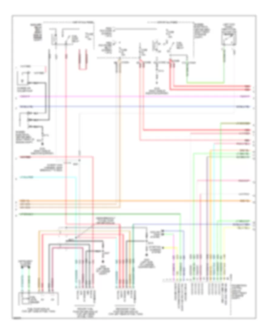
4.0L, Engine Performance Wiring Diagram (4 of 5) for Ford Mustang 2007
List of elements for 4.0L, Engine Performance Wiring Diagram (4 of 5) for Ford Mustang 2007:
- (left side of transmission) digital transmission range (dtr) sensor
- (near breakout to heated oxygen sensor 12)
- Automatic transmission
- C175t
- Dtr sens tr1
- Dtr sens tr2
- Dtr sens tr3a
- Dtr sens tr4
- Ho2s 12 ctrl
- Ho2s 12 sig
- Ho2s 22 ctrl
- Ho2s 22 sig
- Iss sens sig
- Oss sens sig
- Pca sol a ctrl
- Pcb sol b ctrl
- Pcc sol c ctrl
- Powertrain control module (right front of engine compt)
- Red
- Red/pnk
- Reverse lmp sw
- Reversing lamps switch (m/t) (left side of trans- mission)
- S106
- Shift sol a ctrl
- Shift sol b ctrl
- Shift sol c ctrl
- Shift sol d ctrl
- Sig rtn
- Tcc sol ctrl
- Tft sens sig
- Tss sens sig
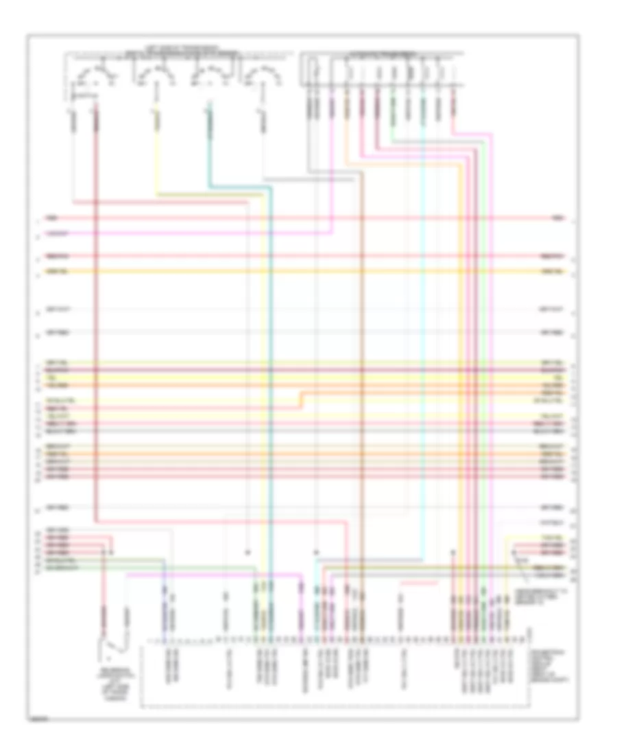
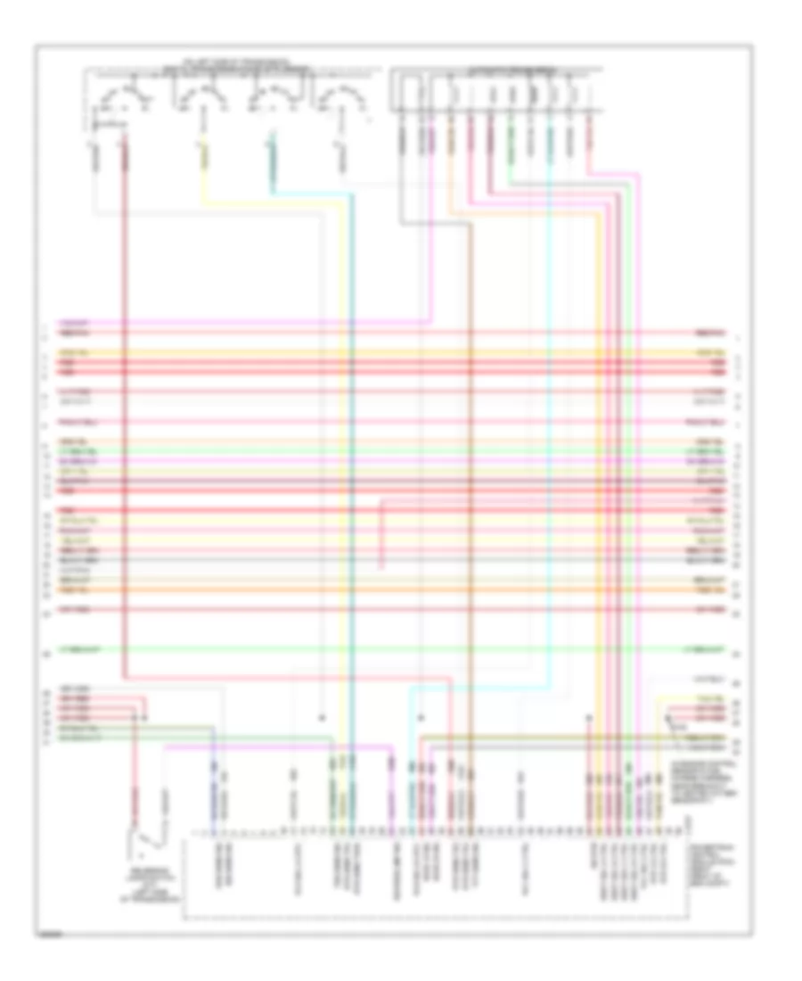
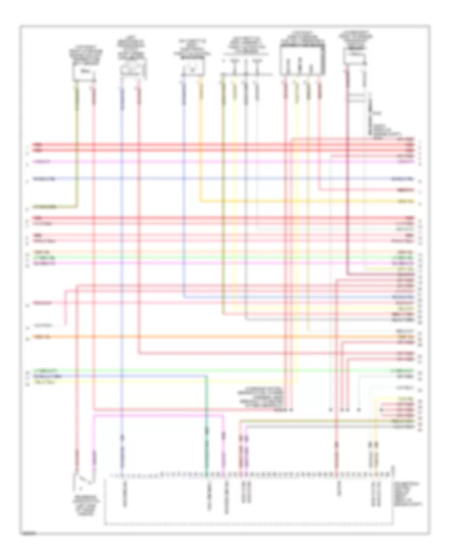
4.0L, Engine Performance Wiring Diagram (5 of 5) for Ford Mustang 2007
List of elements for 4.0L, Engine Performance Wiring Diagram (5 of 5) for Ford Mustang 2007:
- (in engine control sensor & fuel charge harness, near breakout to egr system module)
- (in engine control sensor & fuel charge harness, near breakout to heated positive crankcase ventilation valve) s107
- (near breakout to heated oxygen sensor 21)
- (right front of engine compt) g102
- (right side of engine compt, on air cleaner assembly) mass air flow/intake air temperature (maf/iat) sensor
- 0555e
- C175e
- Camshaft position sensor (left side of engine)
- Ckp pos sens +
- Ckp pos sens -
- Cmp pos sens
- Dpfe
- Dpfe sens sig
- Egr sys mod in
- Egr system module (top center of engine)
- Etc motor +
- Etc motor -
- Etc ref
- Evr ctrl
- Evr-
- Fuel inj 1 ctrl
- Fuel inj 2 ctrl
- Fuel inj 3 ctrl
- Fuel inj 4 ctrl
- Fuel inj 5 ctrl
- Fuel inj 6 ctrl
- Fuel injectors (1, 2 & 3: top right side of engine) (4, 5 & 6: top left side of engine)
- Fuel rail press
- Gnd
- Heated oxygen sensor (ho2s) 11 (in exhaust manifold, above flange on inboard side)
- Heated oxygen sensor (ho2s) 12 (in right rear exhaust, rear of catalytic converter)
- Heated oxygen sensor (ho2s) 21 (in exhaust manifold, above flange on inboard side)
- Heated oxygen sensor (ho2s) 22 (lower left rear of engine, in exhaust manifold)
- Ho2s 11 ctrl
- Ho2s 11 sig
- Ho2s 21 lf
- Htr21 lf
- Iat sens sig
- Inj pwrm
- Knock sens 1 +
- Knock sens 1 -
- Maf sig
- Maf sig rtn
- Map
- Powertrain control module (right front of engine compt)
- Red
- Red/pnk
- Ref volt
- S101
- S102
- Sig rtn
- Tan
- Tps sig 1
- Tps sig 2
- Vpwr
- Vsupp
4.6L
4.6L, Engine Performance Wiring Diagram (1 of 6) for Ford Mustang 2007
List of elements for 4.6L, Engine Performance Wiring Diagram (1 of 6) for Ford Mustang 2007:
- (in body
- (in body main harness, near breakout to c211)
- 57o
- Accel ped pos 1
- Accel ped pos 2
- Accel ped pos 3
- Accelerator pedal position sensor (below left side of dash)
- Accp
- Accs
- Air bag mntr
- Air conditioning system
- Anti-theft system
- App1
- App2
- App3
- Boo
- Brake pedal position switch (on brake pedal support)
- Brk ped pos sw
- Bussed electrical center (bec) (right front of engine compt)
- C1035a c12
- C1035b red
- C175b
- Clutch deact sw
- Cpp
- Cruise control system
- Data link connector (dlc) (under left side of dash)
- Drv pmp fuel mntr
- Dual pres sw
- Etc ref1
- Etc ref2
- Etc rtn
- Evap can vnt vlv
- Evap canister purge valve (left rear of engine compt)
- Evap canister vent control solenoid (left rear of vehicle)
- Exterior lights system
- F6 red
- Fuel pmp drv mod
- Fuel pump relay
- Fuel tank press
- Fuel tank pressure (ftp) sensor (left rear of vehicle, on fuel tank)
- Fuse 10a
- Fuse 15a
- Fuse 5a
- G100 (right side of radiator support)
- G102 (right front of engine compt)
- G103 (right front of engine compt)
- Generator com
- Ground
- Hot at all times
- Hot in start or run
- Hs can +
- Hs can -
- Inertia fuel shutoff (ifs) switch (left kick panel)
- Isp-r
- Kapwr
- Main harness, near breakout to left front wheel speed sensor)
- Mod program sig
- Pcm power diode
- Pcm rc
- Powertrain control module (pcm) (right front of engine compt)
- Red
- Red/pnk
- Ref voltage
- Rx sig
- S113
- S114 (early production)
- S115
- S212
- S225
- S227
- Shift interlock system
- Sig rtn
- Sig trn
- Smart junction box (sjb) (right kick panel)
- Spd ctrl sw rtn
- Spd ctrl sw sig
- Starter rly ctrl
- Starter rly feed
- Starting/ charging system
- Starting/charging system
- Stop lamp sw
- Tan/red
- Vpwr
4.6L, Engine Performance Wiring Diagram (2 of 6) for Ford Mustang 2007
List of elements for 4.6L, Engine Performance Wiring Diagram (2 of 6) for Ford Mustang 2007:
- (at clutch pedal bracket) clutch pedal position switch
- (on clutch pedal support) deactivator switch
- A/c clt rly ctrl
- Bussed electrical center (bec) (right front of engine compt)
- C1035a c11
- C1035b
- C1035b a6
- C1035b e5
- C1035b red
- C175e
- Coil on plug 1 ctrl
- Coil on plug 2 ctrl
- Coil on plug 3 ctrl
- Coil on plug 4 ctrl
- Coil on plug 5 ctrl
- Coil on plug 6 ctrl
- Coil on plug 7 ctrl
- Coil on plug 8 ctrl
- Coolinf fan hi
- Coolinf fan lo
- Cooling fans system
- D5 red
- Evap can pur vlv
- Fp ctrl
- Fp monitor
- Fp power
- Fp rtn
- Fuel pump driver module (underside of luggage compt)
- Fuel rail temp sig
- Fuel tank unit (left rear of vehicle, in fuel tank)
- Fuse 15a
- G204 (left kick panel)
- G400 (left rear of luggage compt)
- Gen mon
- Gnd
- Hot at all times
- Instrument cluster system
- Nca
- Pcm power relay
- Powertrain control module (pcm) (right front of engine compt)
- Red
- S407
- Starting/ charging system
- Transmission shift selector (under center console)
- Vpwr
4.6L, Engine Performance Wiring Diagram (3 of 6) for Ford Mustang 2007
List of elements for 4.6L, Engine Performance Wiring Diagram (3 of 6) for Ford Mustang 2007:
- (left rear side of transmission) output shaft speed (oss) sensor
- (on throttle body assembly)
- (right front of engine compt) g102
- (top left side of transmission) intermediate shaft speed (iss) sensor
- (top left side of transmission) turbine shaft speed (tss) sensor
- Crankshaft position sensor (on center front of engine, below right side of water pump)
- Electronic throttle control (etc) motor (on throttle body)
- Fuel rail pressure & temperature sensor (top left side of engine)
- Nca
- Pressure sn
- Red
- Red/pnk
- Sig rtn
- Temp sn
- Throttle position sensor (tps)
- Vref
4.6L, Engine Performance Wiring Diagram (4 of 6) for Ford Mustang 2007
List of elements for 4.6L, Engine Performance Wiring Diagram (4 of 6) for Ford Mustang 2007:
- (in engine control sensor & fuel charge harness, near breakout to heated oxygen sensor #11)
- (on left side of transmission) digital transmission range (dtr) sensor
- Automatic transmission
- C175t
- Dtr sens tr2
- Dtr sens tr3a
- Dtr sens tr4
- Ho2s 12 sig
- Ho2s 22 sig
- Htr 12 ctrl
- Htr 22 ctrl
- Iss sens sig
- Oss sens sig
- Pca sol a crtl
- Pcb sol b crtl
- Pcc sol c ctrl
- Powertrain control module (pcm) (right front of eng compt)
- Red
- Red/pnk
- Reverse lmp sw
- Reversing lamps switch (m/t) (left side of transmission)
- S106
- Shift sol a ctrl
- Shift sol b ctrl
- Shift sol c ctrl
- Shift sol d ctrl
- Sig rtn
- Tcc sol ctrl
- Tft sens sig
- Tss sens sig
4.6L, Engine Performance Wiring Diagram (5 of 6) for Ford Mustang 2007
List of elements for 4.6L, Engine Performance Wiring Diagram (5 of 6) for Ford Mustang 2007:
- (front of left cylinder head) variable valve timing solenoid 2
- (front of right cylinder head) variable valve timing solenoid 1
- (in engine control sensor & fuel charge harness, near breakout to ignition coil) s104
- (left front of engine) camshaft position sensor 2
- (rear of right cylinder head) knock sensor
- (right rear of engine compt) intake manifold runner control (imrc) module
- (right rear of engine) cylinder head temperature sensor
- Coil on plugs
- G102 (right front of engine compt)
- Ignition transformer capacitor 1 (right front of engine)
- Ignition transformer capacitor 2 (left front of engine)
- Nca
- Red
- Red/pnk
- S119 (in engine control sensor & fuel charge harness, near breakout to bussed electrical center)
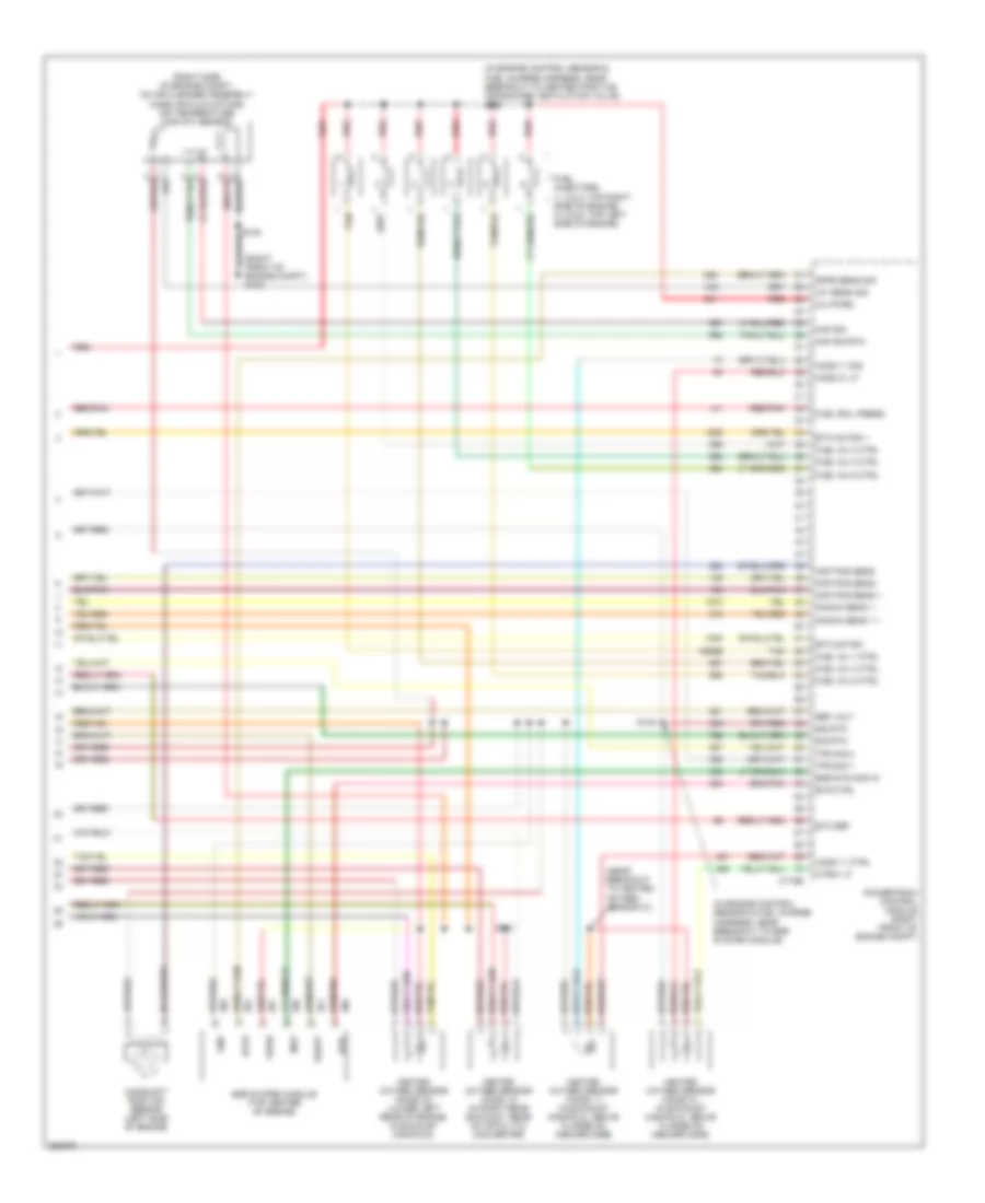
4.6L, Engine Performance Wiring Diagram (6 of 6) for Ford Mustang 2007
List of elements for 4.6L, Engine Performance Wiring Diagram (6 of 6) for Ford Mustang 2007:
- 357
- (in engine control sensor & fuel charge harness, near breakout to fuel injector 4) s107
- (right front of engine compt) g102
- C175e
- Camshaft position sensor 1 (right front of engine)
- Ckp pos sens +
- Ckp pos sens -
- Cmp pos sens 1
- Cmp pos sens 2
- Cyl head temp sens
- Etc motor +/-
- Etc motor +/_
- Fuel inj 1 ctrl
- Fuel inj 2 ctrl
- Fuel inj 3 ctrl
- Fuel inj 4 ctrl
- Fuel inj 5 ctrl
- Fuel inj 6 ctrl
- Fuel inj 7 ctrl
- Fuel inj 8 ctrl
- Fuel injectors (1,2,3,4: top right side of engine) (5,6,7,8: top left side of engine)
- Fuel rail press
- Heated oxygen sensor (ho2s) 11 (in exhaust manifold, above flange on inboard side)
- Heated oxygen sensor (ho2s) 12 (in right rear exhaust, rear of catalytic converter)
- Heated oxygen sensor (ho2s) 21 (in exhaust manifold, above flange on inboard side)
- Heated oxygen sensor (ho2s) 22 (lower left rear of engine, in exhaust manifold)
- Ho2s 11 sig
- Ho2s 21 sig
- Htr 11 ctrl
- Htr 21 ctrl
- Imtv ctrl
- Inj pwrm
- Intake air temp
- Knock sens 1 +
- Knock sens 1 -
- Knock sens 2 +
- Knock sens 2 -
- Maf sig
- Maf sig rtn
- Mass air flow/ intake air temperature (maf/iat) sensor (on air cleaner assembly)
- Powertrain control module (pcm) (right front of engine compt)
- Red
- Red/pnk
- Ref volt
- S101 (in engine control sensor & fuel charge harness, near breakout to fuel injector 4)
- S102
- S109 (in engine control sensor & fuel charge harness, near breakout to c134)
- Sig rtn
- Tan
- Tan/red
- Tps ref volt
- Tps sig 1
- Tps sig 2
- Var vlv timing 1
- Var vlv timing 2
5.4L SUPERCHARGED
5.4L Supercharged, Engine Performance Wiring Diagram (1 of 5) for Ford Mustang 2007
List of elements for 5.4L Supercharged, Engine Performance Wiring Diagram (1 of 5) for Ford Mustang 2007:
- (late production) (early production)
- (late production: near breakout to g204) (early production: near breakout to left front wheel speed sensor) s213 s113
- (near breakout to c211)
- 57o
- Accel ped pos 1
- Accel ped pos 2
- Accel ped pos 3
- Accelerator pedal position sensor (below left side of dash)
- Accr
- Accs
- Acp
- Air conditioning system
- Alternator com
- Anti-theft system
- App1
- App2
- App3
- Auxiliary relay box 1 (right side of engine
- Brake pedal position switch (on brake pedal support)
- Brk ped pos sw
- Bussed electrical center (bec) (right front of engine compt)
- C175b
- Charge air cooler pump relay
- Clutch deact sw
- Clutch pedal position switch (at clutch pedal bracket)
- Compt)
- Cpp
- Cruise control system
- Cruise control system anti-theft system starting/charging system
- Data link connector (dlc) (under left side of dash)
- Deacti- vator switch (on clutch pedal support)
- Etcref1
- Etcref2
- Etcrtn
- Evap can vnt sol
- Evap canister purge valve (left rear of engine compt)
- Evap canister vent control solenoid (left rear of vehicle)
- Feps
- Fuel pmp drv mod
- Fuel pmp mntr 1
- Fuel tank pressure (ftp) sensor (left rear of vehicle, on fuel tank)
- Fuse 10a
- Fuse 15a
- Fuse 5a
- G102 (right front of engine compt)
- G103 (right front of engine compt)
- G204 (left kick panel)
- Ground
- Hot at all times
- Hot in run or start
- Hs can +
- Hs can -
- Isp-r
- Kapwr
- Pcm diode
- Pcm power relay
- Pcm pwr rly out
- Pcm rc
- Powertrain control module (right front of engine compt)
- Red/pnk
- Ref voltage
- Reference voltage
- Rx sig
- S115
- S212
- S214 s114 (late production: near breakout to left front channel subwoofer amplifier) (early production: near breakout to left front wheel speed sensor)
- S215
- S225
- Sensor signal
- Sig return
- Sig trn
- Sigrtn
- Smart junction box (sjb) (right kick panel)
- Spd ctrl sw rtn
- Spd ctrl sw sig
- Starter rly ctrl
- Starter rly feed
- Starting/ charging system
- Starting/charging system exterior lights system
- Stop lamp sw sig
- Subwoofer amplifier) s227
- Tan/red
- Tas
- To fuel pump relay (diagram 2 of 5)
- To fuse 42 15a (diagram 2 of 5)
- Tx sig
5.4L Supercharged, Engine Performance Wiring Diagram (2 of 5) for Ford Mustang 2007
List of elements for 5.4L Supercharged, Engine Performance Wiring Diagram (2 of 5) for Ford Mustang 2007:
- (in body main harness, near breakout to g204)
- (left kick panel) inertia fuel shutoff (ifs) switch
- (near breakout to fuel pump driver module)
- Alternator monitor
- Auxiliary auxiliary relay relay box 1 box 1 (right (right side of side of engine engine compt)
- Bat
- Bussed electrical center (bec) (right front of engine compt)
- C1035b f6 red
- C1035b red
- C12
- C175e
- Cd a cyl1
- Cd b cyl3
- Cd c cyl7
- Cd d cyl2
- Cd e cyl6
- Cd f cyl5
- Cd g cyl4
- Cd h cyl8
- Charge air cooler pump
- Cooling fan hi
- Cooling fan lo
- Cooling fans system
- D5 red
- Eng clt temp sn
- Evap can prg vlv ctrl
- Fp ctrl
- Fp monitor
- Fp power
- Fp rtn
- From b pcm power relay (diagram 1 of 5)
- From pcm diode (diagram 1 of 5)
- Fuel level sender
- Fuel pump module (top left side of fuel tank)
- Fuel pump relay
- Fuel rail temp sig
- Fuse 15a
- G100 (right side of radiator support)
- G400 (left rear of luggage compt)
- G403 (left side of luggage compartment)
- Gnd
- Hot at all times
- Instrument cluster system
- Nca
- Powertrain control module (right front of engine compt)
- Primary fuel pump driver module (top left rear of fuel tank)
- Red
- S112
- S221
- S415
- S417
- Secondary fuel pump driver module (top left rear of fuel tank)
- Starting/ charging system
- Vbatt
5.4L Supercharged, Engine Performance Wiring Diagram (3 of 5) for Ford Mustang 2007
List of elements for 5.4L Supercharged, Engine Performance Wiring Diagram (3 of 5) for Ford Mustang 2007:
- (in engine control sensor & fuel charge harness, near breakout to heated oxygen sensor 21) s102
- (left rear side of transmission) output shaft speed (oss) sensor
- (lower right front of engine) crankshaft position sensor
- (on throttle body assembly) throttle position (tp) sensor
- (on throttle body) electronic throttle control (etc) motor
- (right front of engine compt) g102
- (top right front of engine) engine coolant temperature (ect) sensor
- (top right side of engine) fuel rail pressure & temperature sensor
- C175t
- Fuel pmp mon 2
- Ho2s 12 ctrl
- Ho2s 12 sig
- Ho2s 22 ctrl
- Ho2s 22 sig
- Nca
- Oss sens sig
- Powertrain control module (right front of engine compt)
- Pressure sn
- Red
- Red/pnk
- Reverse lmp sw
- Reversing lamps switch (left side of trans- mission)
- Sig rtn
- Temp sn
- Vref
5.4L Supercharged, Engine Performance Wiring Diagram (4 of 5) for Ford Mustang 2007
List of elements for 5.4L Supercharged, Engine Performance Wiring Diagram (4 of 5) for Ford Mustang 2007:
- (left side of manual transmission) reverse lockout solenoid
- (rear of right cylinder bank) cylinder head temperature sensor
- (top left front of engine) air charge temperature (act) sensor
- (top right front of engine) heated positive crankcase ventilation (pcv) valve
- Bussed electrical center (bec) (right front of engine compt)
- C1035b f8
- Coil on plugs
- F5 c1035c
- G100 (right side of radiator support)
- Ignition transformer capacitor 1 (top right side of engine)
- Ignition transformer capacitor 2 (left rear of engine)
- Nca
- Red
- Red/pnk
- S104
- S112
- S119 (in engine control sensor & fuel charge harness, near breakout to ignition transformer capacitor 1)
5.4L Supercharged, Engine Performance Wiring Diagram (5 of 5) for Ford Mustang 2007
List of elements for 5.4L Supercharged, Engine Performance Wiring Diagram (5 of 5) for Ford Mustang 2007:
- (in engine control sensor & fuel charge harness, near breakout to c1164) s107
- (near breakout to bussed electrical center)
- (near breakout to c1164)
- (right front of engine compt) g102
- Anti-lock brakes system
- Brake padal sw
- C175e
- Camshaft position sensor 1 (left front of engine)
- Cid 1rt
- Ckp pos sens +
- Ckp pos sens -
- Cyl head temp sens
- Dpfe
- Dpfe sn
- Egr system module (top center of engine)
- Egr vacuum reg
- Etc ref
- Etc rtn
- Etc throttle motor+
- Etc throttle motor-
- Evr-
- Fuel inj 1 ctrl
- Fuel inj 2 ctrl
- Fuel inj 3 ctrl
- Fuel inj 4 ctrl
- Fuel inj 5 ctrl
- Fuel inj 6 ctrl
- Fuel inj 7 ctrl
- Fuel inj 8 ctrl
- Fuel injectors (1, 2, 3 & 4: top right side of engine) (5, 6, 7 & 8: top left side of engine)
- Fuel rail press
- Heated oxygen sensor (ho2s) 11 (in exhaust manifold, above flange on inboard side)
- Heated oxygen sensor (ho2s) 12 (in right rear exhaust, rear of catalytic converter)
- Heated oxygen sensor (ho2s) 21 (in exhaust manifold, above flange on inboard side)
- Heated oxygen sensor (ho2s) 22 (lower left rear of engine, in exhaust manifold)
- Ho2s 11 ctrl
- Ho2s 11 sig
- Ho2s 21 ctrl
- Ho2s 21 sig
- Iat 2
- Iat sens sig
- Inj pwrm
- Maf sig
- Maf sig rtn
- Map
- Map sensor
- Mass air flow/ intake air temperature (maf/iat) sensor (on air cleaner assembly)
- Pcv heater
- Powertrain control module (right front of engine compt)
- Red
- Red/pnk
- Ref volt
- Rs lockout
- S101 (in engine control sensor & fuel charge harness, near breakout to ignition transformer capacitor 1)
- S103
- S106
- S109 (in engine control sensor & fuel charge harness, near breakout to fuel injector 8)
- Sc intercooler
- Sig rtn
- Tan
- Tan/red
- Tps sig 1
- Tps sig 2
- Vpwr
- Vref