ENGINE PERFORMANCE
3.8L
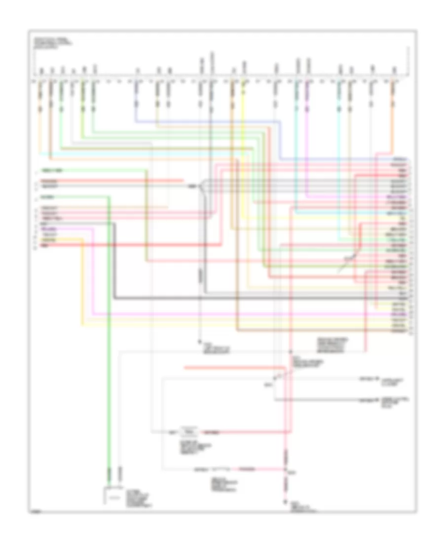
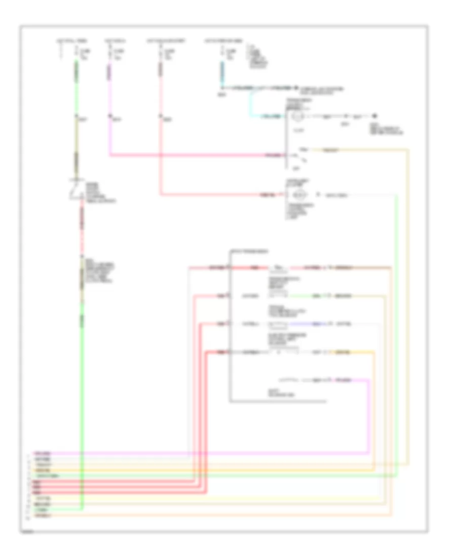
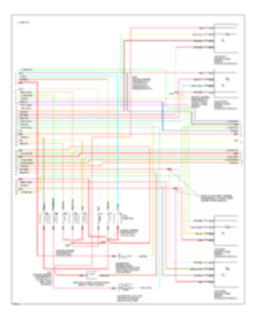
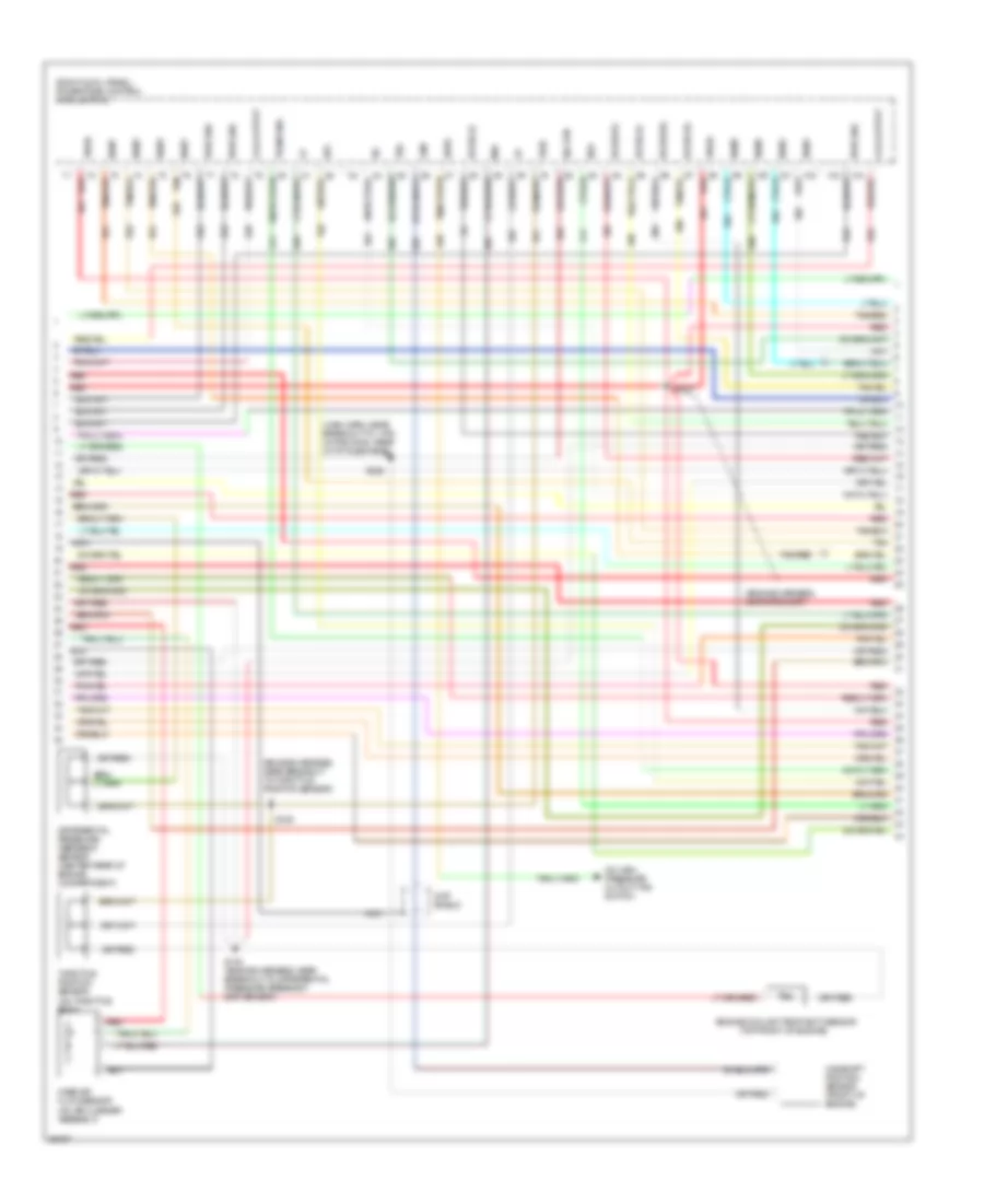
3.8L, Engine Performance Wiring Diagrams (1 of 6) for Ford Mustang GT 1997

List of elements for 3.8L, Engine Performance Wiring Diagrams (1 of 6) for Ford Mustang GT 1997:
- (left front of engine compt)
- (right cowl panel) powertrain control module (pcm)
- (top front of engine)
- C 1995 vftc
- C250
- C251
- Ckp shield
- Ckp+
- Ckp-
- Coil output
- Crankshaft position sensor (center front of engine)
- Cse gnd
- Data link connector (behind i/p, right
- Dlc
- Dlc(+)
- Dlc(-)
- Evap sensor
- Evaporative emissions (evap) purge flow sensor (right rear of engine compartment)
- Fuse 10a
- Fuse 20a
- G100
- G203 (behind i/p, at right cowl)
- Gnd
- Ho2s(rr)
- Hot in run or start
- I/p fuse panel (left of steering column)
- Ignition coil
- Instrument cluster
- Malfunction indicator lamp
- Mil
- Nca
- Of steering column)
- Radio interference capacitor (top right front of engine)
- Red
- S129
- S142
- S204
- S228
- Spark plugs
- Ss1
- Ss2
- Tach
- Tcs
- Vss(-)
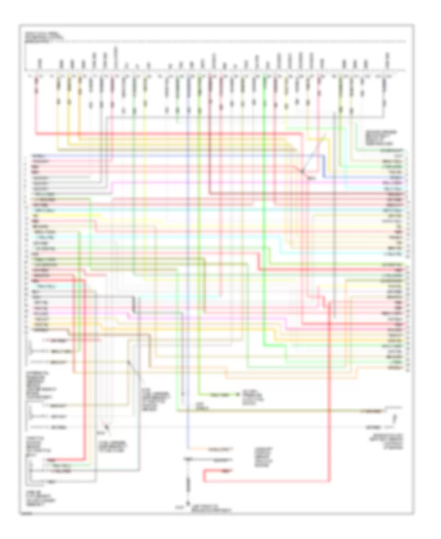
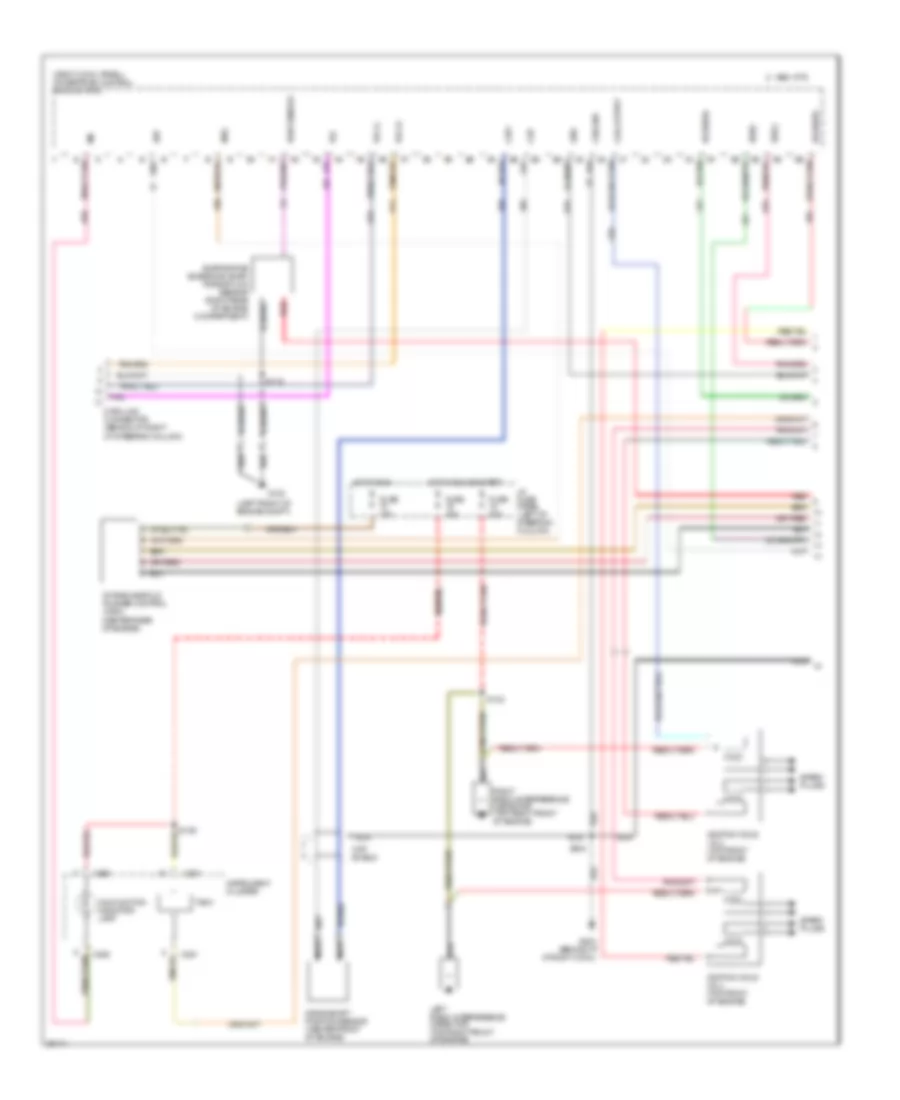
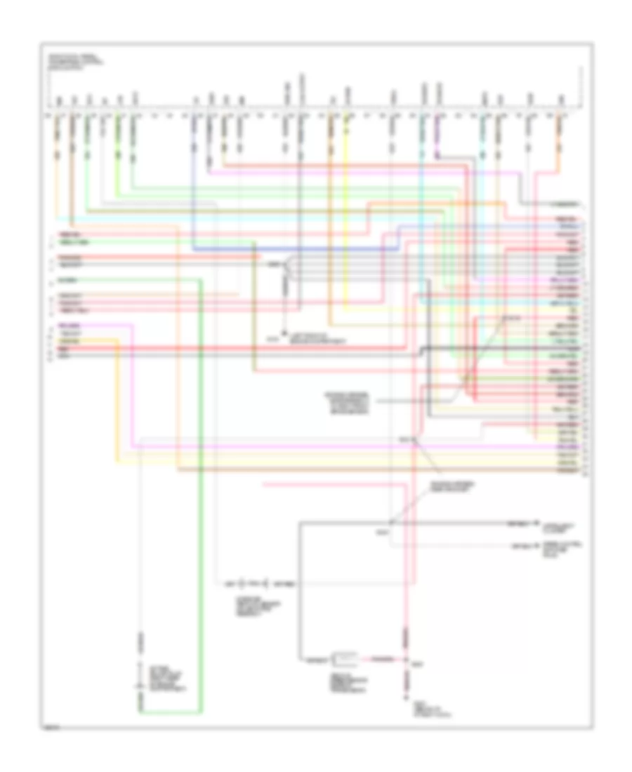
3.8L, Engine Performance Wiring Diagrams (2 of 6) for Ford Mustang GT 1997
List of elements for 3.8L, Engine Performance Wiring Diagrams (2 of 6) for Ford Mustang GT 1997:
- (engine harness, near breakout to right front brake sensor)
- (right cowl panel) powertrain control module (pcm)
- Accs
- Canp
- Coil output
- Ecs
- Egr
- Evr
- Fpm
- G100 (left front of engine compt)
- G203 (behind i/p, at right cowl)
- Ho2s(lr)
- Ho2s(rf)
- Iat
- Idm
- Instrument cluster
- Intake air temp (iat) sensor (on air intake assembly)
- Ka pwr
- Lfc
- Maf
- Mlps
- Nca
- Octane adjust plug (right rear of engine compartment)
- Pwr gnd
- Red
- S116
- S121 (engine harness, near grommet)
- S235
- S240
- S250
- Speed control amplifier pin #3
- Tcc
- Tot
- Vehicle speed sensor (rear of transmission)
- Vss(+)
- Wac
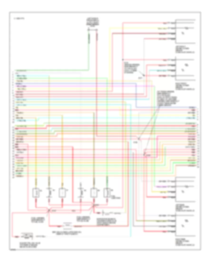
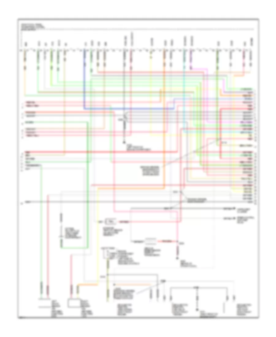
3.8L, Engine Performance Wiring Diagrams (3 of 6) for Ford Mustang GT 1997
List of elements for 3.8L, Engine Performance Wiring Diagrams (3 of 6) for Ford Mustang GT 1997:
- (engine harness, behind right side of i/p, near grommet)
- (front of engine)
- (fuel harness, near breakout to fuel inj #6)
- (left front of engine compartment)
- (on air cleaner assembly)
- (on throttle body)
- (right cowl panel) powertrain control module (pcm)
- A/c high pressure cutout fan switch
- Ahps
- Boo
- Camshaft position sensor
- Cmp
- Cmp shield
- Coil output
- Differential pressure feedback sensor (center rear of engine compartment)
- Engine coolant temp (ect) sensor (top front of engine)
- Epc
- G100
- Ho2s(lf)
- Ho2s(lr)
- Ho2s(rf)
- Ho2s(rr)
- Iac
- Inj#1
- Inj#2
- Inj#3
- Inj#4
- Inj#5
- Inj#6
- Maf
- Mass air flow sensor
- Nca
- Pwr gnd
- Red
- S129 (fuel harness, near breakout to throttle position sensor)
- S130
- S142
- S234
- Sig rtn
- Tan
- Tcl
- Throttle position sensor
- Tss
- Vpwr
- Vref
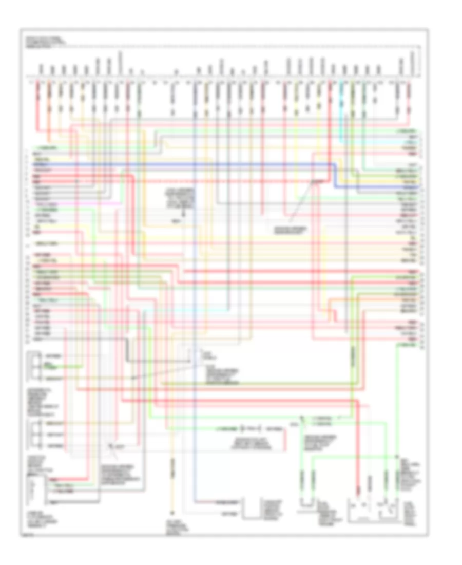
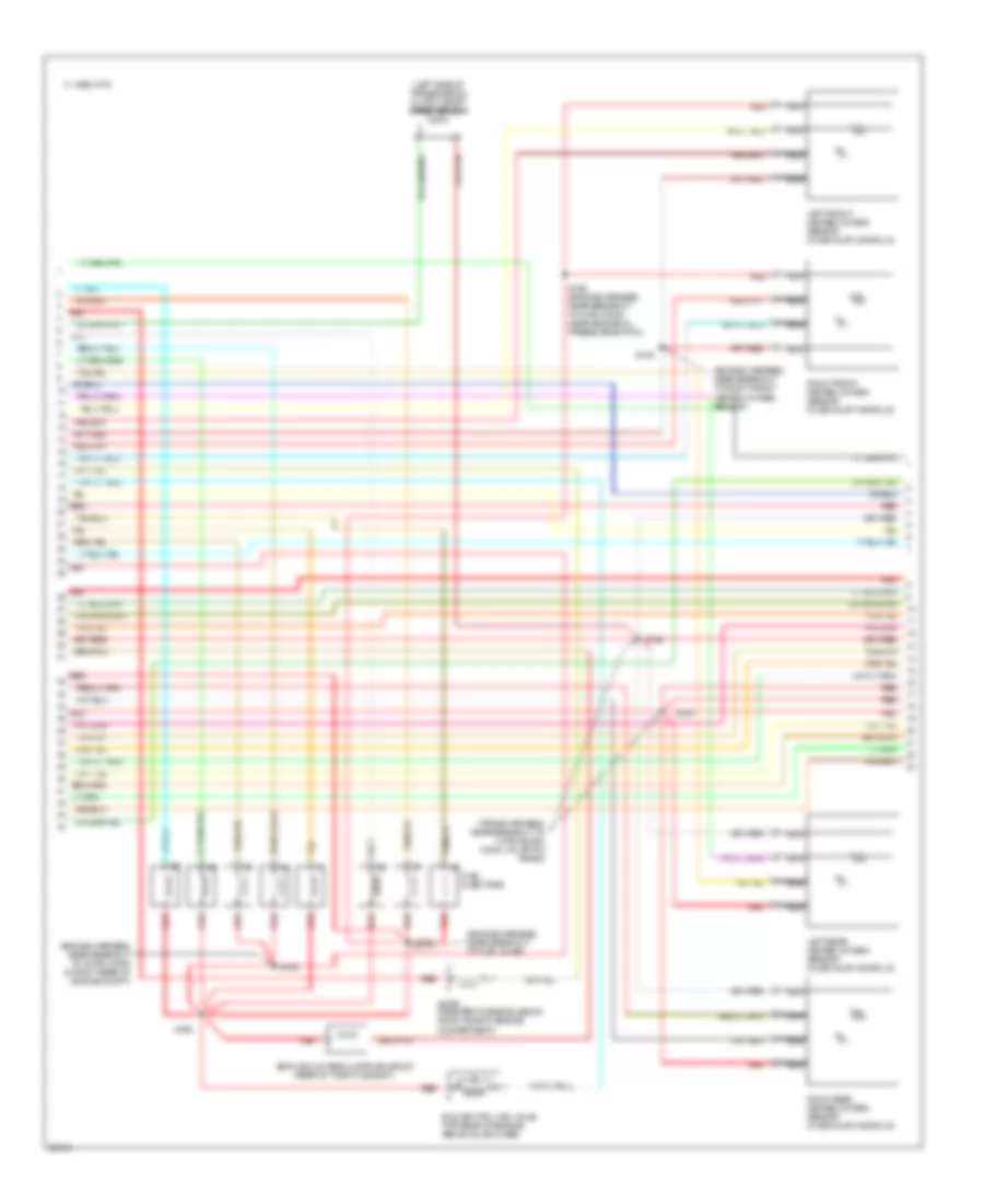
3.8L, Engine Performance Wiring Diagrams (4 of 6) for Ford Mustang GT 1997
List of elements for 3.8L, Engine Performance Wiring Diagrams (4 of 6) for Ford Mustang GT 1997:
- (a/t: trans harness, near breakout to 10-pin black conn, on 4r70w trans; m/t: back up lamp feed harness, near breakout to right rear heated oxygen sensor)
- (fuel harness, near breakout to fuel inj #2)
- (fuel harness, near breakout to fuel inj #5)
- (left side of transmission) output shaft speed sensor
- (rear of throttle body)
- C 1995 vftc
- Egr vacuum regulator (evr) sol
- Evaporative emission canister purge valve (right side of engine compartment)
- Fuel injectors
- Idle air ctrl (iac) valve (top rear of engine above valve cover)
- Left front heated oxygen sensor (in exhaust manifold)
- Left rear heated oxygen sensor (in exhaust manifold)
- Nca
- Red
- Right front heated oxygen sensor (in exhaust manifold)
- Right rear heated oxygen sensor (in exhaust manifold)
- S123
- S124
- S125
- S126
- S137
- S138 (engine harness, near breakout to 8-pin black conn, lh rear of engine)
- Tan
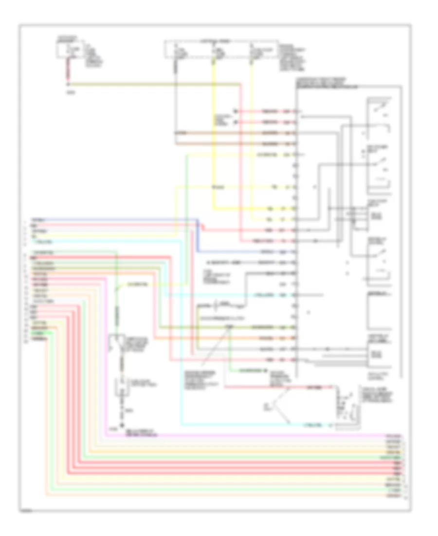
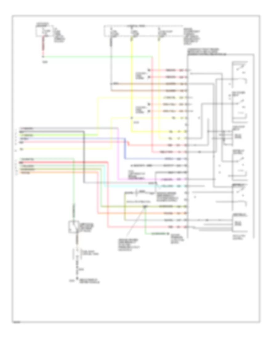
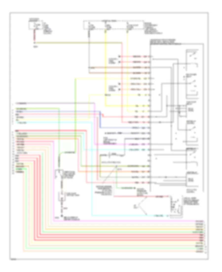
3.8L, Engine Performance Wiring Diagrams (5 of 6) for Ford Mustang GT 1997
List of elements for 3.8L, Engine Performance Wiring Diagrams (5 of 6) for Ford Mustang GT 1997:
- (below rear of center console)
- (engine harness, near breakout to a/c high pressure cutout/ fan switch)
- (inside right front fender, behind air filter housing) constant control relay module
- A/c clutch
- A/c compressor clutch
- A/c high pressure cutout fan switch
- A/t only
- Control
- Cooling fans system
- Edf relay
- Edf relay control
- Eec fuse 20a
- Engine compartment fuse box (left side of engine compt, forward of strut tower)
- Fan fuse 60a
- Fuel pump (on fuel tank)
- Fuel pump fuse 20a
- Fuel pump relay
- Fuse 20a
- G100 (left front of engine compartment)
- G302
- Hedf relay (not used)
- Hot at all times
- Hot in run or start
- I/p fuse panel (left of steering column)
- Inertia fuel shut off sw (left rear of trunk)
- Manual lever position sensor (rear left side of transmission)
- Pcm power relay
- Red
- S102
- S108
- S115
- S119
- S228
- S408
- Solid state
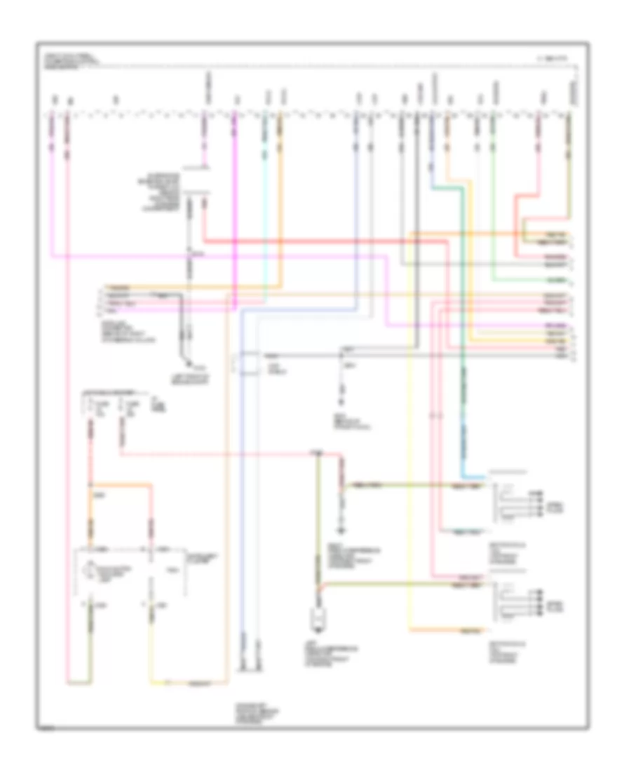
3.8L, Engine Performance Wiring Diagrams (6 of 6) for Ford Mustang GT 1997
List of elements for 3.8L, Engine Performance Wiring Diagrams (6 of 6) for Ford Mustang GT 1997:
- 4r70w transmission
- Brake on/off switch (on brake pedal support)
- Electric pressure control (epc) solenoid
- Fuse 10a
- Fuse 15a
- G302 (below rear of center console)
- Hot at all times
- Hot in park or head
- Hot in run
- Hot in run or start
- I/p fuse panel (left of steering column)
- Illum
- Instrument cluster
- Interior lights system (fog lamp switch)
- Off
- Red
- S207
- S219
- S229
- S230
- S232 (body harness, near breakout to 2-pin gray conn, near clutch pedal)
- S301
- Shift solenoid (ss)
- Torque converter clutch (tcc) solenoid
- Transmission control indicator lamp
- Transmission control switch
- Transmission oil temp (tot) sensor
4.6L
4.6L DOHC, Engine Performance Wiring Diagrams (1 of 5) for Ford Mustang GT 1997
List of elements for 4.6L DOHC, Engine Performance Wiring Diagrams (1 of 5) for Ford Mustang GT 1997:
- (center rear of engine)
- (left front of engine compt)
- (right cowl panel) powertrain control module (pcm)
- C 1995 vftc
- C250
- C251
- Ckp shield
- Ckp+
- Ckp-
- Coil output
- Crankshaft position sensor (center front of engine)
- Cse gnd
- Data link connector (behind i/p, right
- Dlc
- Dlc(+)
- Dlc(-)
- Eap
- Evap sensor
- Evaporative emissions (evap) purge flow sensor (right rear of engine compartment)
- Fuse 10a
- Fuse 15a
- Fuse 20a
- G100
- G203 (behind i/p at right cowl)
- Gnd
- Ho2s(rr)
- Hot in run
- Hot in run or start
- I/p fuse panel (left of steering column)
- Ignition coils 1 & 2 (top front of engine)
- Ignition coils 3 & 4 (top front of engine)
- Imrc
- Instrument cluster
- Intake manifold runner control (imrc)
- Ks #2
- Left radio interference capacitor (top right front of engine)
- Malfunction indicator lamp
- Mil
- Nca
- Of steering column)
- Red
- Right radio interference capacitor (top right front of engine)
- S115
- S129
- S132
- S204
- Spark plugs
- Tach
- Vss(-)
4.6L DOHC, Engine Performance Wiring Diagrams (2 of 5) for Ford Mustang GT 1997
List of elements for 4.6L DOHC, Engine Performance Wiring Diagrams (2 of 5) for Ford Mustang GT 1997:
- (between injectors 1 & 2)
- (between injectors 5 & 6)
- (engine harness, near breakout to right front brake sensor)
- (engine harness, near grommet)
- (right cowl panel) powertrain control module (pcm)
- Accs
- Air injection reaction (air) pump (right front fender)
- Air injection reaction (air) relay (right front fender)
- Air injection reaction (airb) bypass (right front fender)
- Air man
- Coil output
- Ecs
- Egr
- Engine compartment fuse box (left side of engine compt, forward of strut)
- Evap
- Evr
- Fpr
- G100 (left front of engine compartment)
- G101 (right front of engine compt)
- G203 (behind i/p, at right cowl)
- Hedf
- Ho2s(lr)
- Ho2s(rf)
- Hot at times
- Iac
- Iat
- Idm
- Instrument cluster
- Intake air temp (iat) sensor (on air intake assembly)
- Ka pwr
- Ks #1
- Left knock sensor (ks)
- Lfc
- Maf
- Nca
- Octane adjust plug (right rear of engine compartment)
- Pwr gnd
- Red
- Right knock sensor (ks)
- S100
- S116
- S121
- S145
- S154
- S155 (engine harness, near breakout to air injection reaction pump)
- S235
- S240
- Speed control amplifier pin #3
- Therm fuse 30a
- Vehicle speed sensor (rear of transmission)
- Vss(+)
- Wac
4.6L DOHC, Engine Performance Wiring Diagrams (3 of 5) for Ford Mustang GT 1997
List of elements for 4.6L DOHC, Engine Performance Wiring Diagrams (3 of 5) for Ford Mustang GT 1997:
- (engine harness, near breakout to differential pressure feedback egr sensor)
- (engine harness, near breakout to fuel pump resistor)
- (engine harness, near grommet)
- (front of engine)
- (main harness, near breakout to 1-pin white conn, rear of i/p fuse panel)
- (on air cleaner assembly)
- (on throttle body)
- (right cowl panel) powertrain control module (pcm)
- 78a
- A/c high pressure cutout/fan switch
- Ahps
- Camshaft position sensor
- Cmp
- Cmp shield
- Coil output
- Differential pressure feedback sensor (center rear of engine compartment)
- Engine coolant temp (ect) sensor (top front of engine)
- Fpc
- Fuel pump relay (right cowl panel)
- Fuel pump resistor (rear of right front fender)
- Ho2s(lf)
- Ho2s(lr)
- Ho2s(rf)
- Ho2s(rr)
- Iac
- Inj#1
- Inj#2
- Inj#3
- Inj#4
- Inj#5
- Inj#6
- Inj#7
- Inj#8
- Maf
- Mass air flow sensor
- Nca
- Pwr gnd
- Red
- S127
- S129 (engine harness, near breakout to throttle position sensor)
- S130
- S153
- S224
- S251 (eng harn, near breakout to 8-pin gray conn, at right cowl)
- Sig rtn
- Tan
- Tan/red
- Throttle position sensor
- Vpwr
- Vref
4.6L DOHC, Engine Performance Wiring Diagrams (4 of 5) for Ford Mustang GT 1997
List of elements for 4.6L DOHC, Engine Performance Wiring Diagrams (4 of 5) for Ford Mustang GT 1997:
- #1 #1 #1 #1 #1 #1
- #3 #3 #3 #3 #3 #3
- #4 #4 #4 #4 #4 #4
- #5 #5 #5 #5 #5 #5
- #6 #6 #6 #6 #6 #6
- (back up lamp feed harness, near breakout to right rear heated oxygen sensor)
- (engine harness, near breakout to fuel inj #2)
- (engine harness, near breakout to fuel inj #8)
- (engine harness, near breakout to right front heated oxygen sensor)
- (rear of throttle body)
- C 1995 vftc
- Egr vacuum regulator solenoid
- Evaporative emission (evap) canister purge valve (right side of engine compartment)
- Fuel injectors
- Idle air ctrl (iac) valve (top rear of engine above valve cover)
- Left front heated oxygen sensor (in exhaust manifold)
- Left rear heated oxygen sensor (in exhaust manifold)
- Nca
- Red
- Red red red red red red
- Right front heated oxygen sensor (in exhaust manifold)
- Right rear heated oxygen sensor (in exhaust manifold)
- S125
- S126
- S139
- S150
- S151 (engine harness, near breakout to egr vacuum regulator solenoid)
- S152
- S168 (engine harness, near breakout to 8-pin conn, near engine oil pressure switch)
- Tan
- Tan/red
4.6L DOHC, Engine Performance Wiring Diagrams (5 of 5) for Ford Mustang GT 1997
List of elements for 4.6L DOHC, Engine Performance Wiring Diagrams (5 of 5) for Ford Mustang GT 1997:
- (below rear of center console)
- (engine harness, near breakout to a/c high pressure cutout/ fan switch)
- (inside right front fender, behind air filter housing) constant control relay module
- A/c clutch
- A/c clutch field coil
- A/c high pressure cutout fan switch
- Control
- Cooling fans system
- Edf relay
- Edf relay control
- Eec fuse 20a
- Engine compartment fuse box (left side of engine compt, forward of strut)
- Fan fuse 60a
- Fuel pump (on fuel tank)
- Fuel pump fuse 20a
- Fuel pump relay
- Fuse 20a
- G100 (left front of engine compartment)
- G302
- Hedf relay
- Hot at all times
- Hot in run or start
- I/p fuse panel (left of steering column)
- Inertia fuel shut off sw (left rear of trunk)
- Near breakout to intake manifold runner control)
- Pcm power relay
- Red
- S102
- S108
- S115
- S119
- S149
- S228
- S408
- Solid state
4.6L SOHC, Engine Performance Wiring Diagrams (1 of 6) for Ford Mustang GT 1997
List of elements for 4.6L SOHC, Engine Performance Wiring Diagrams (1 of 6) for Ford Mustang GT 1997:
- (left front of engine compt)
- (right cowl panel) powertrain control module (pcm)
- C 1995 vftc
- C250
- C251
- Ckp shield
- Ckp+
- Ckp-
- Coil output
- Crankshaft position sensor (center front of engine)
- Cse gnd
- Data link connector (behind i/p, right
- Dlc
- Dlc(+)
- Dlc(-)
- Eap
- Evap sensor
- Evaporative emissions (evap) purge flow sensor (right rear of engine compartment)
- Fuse 10a
- Fuse 20a
- G100
- G203 (behind i/p at right cowl)
- Gnd
- Ho2s(rr)
- Hot in run or start
- I/p fuse panel
- Ignition coils 1 & 2 (top front of engine)
- Ignition coils 3 & 4 (top front of engine)
- Instrument cluster
- Left radio interference capacitor (top right front of engine)
- Malfunction indicator lamp
- Mil
- Nca
- Of steering column)
- Red
- Right radio interference capacitor (top right front of engine)
- S115
- S132
- S204
- S229
- Spark plugs
- Ss1
- Ss2
- Tach
- Tcs
- Vss(-)
4.6L SOHC, Engine Performance Wiring Diagrams (2 of 6) for Ford Mustang GT 1997
List of elements for 4.6L SOHC, Engine Performance Wiring Diagrams (2 of 6) for Ford Mustang GT 1997:
- (engine harness, near breakout to right front brake sensor)
- (engine harness, near grommet)
- (left front of engine compartment)
- (right cowl panel) powertrain control module (pcm)
- Accs
- Coil output
- Ecs
- Egr
- Evap
- Evr
- Fpr
- G100
- G203 (behind i/p, at right cowl)
- Hedf
- Ho2s(lr)
- Ho2s(rf)
- Iat
- Idm
- Instrument cluster
- Intake air temp (iat) sensor (on air intake assembly)
- Ka pwr
- Lfc
- Maf
- Mlps
- Nca
- Octane adjust plug (right rear of engine compartment)
- Pwr gnd
- Red
- S116
- S121
- S235
- S240
- S250
- Speed control amplifier pin #3
- Tcc
- Tot
- Vehicle speed sensor (rear of transmission)
- Vss(+)
- Wac
4.6L SOHC, Engine Performance Wiring Diagrams (3 of 6) for Ford Mustang GT 1997
List of elements for 4.6L SOHC, Engine Performance Wiring Diagrams (3 of 6) for Ford Mustang GT 1997:
- (engine harness, near breakout to throttle position sensor)
- (engine harness, near grommet)
- (front of engine)
- (main harn, near breakout to 1-pin white conn, rear of i/p fuse panel)
- (on air cleaner assembly)
- (on throttle body)
- (right cowl panel) powertrain control module (pcm)
- (top front of engine)
- A/c high pressure cutout fan switch
- Ahps
- Boo
- Camshaft position sensor
- Cmp
- Cmp shield
- Coil output
- Differential pressure feedback sensor (center rear of engine compartment)
- Engine coolant temp (ect) sensor
- Epc
- Ho2s(lf)
- Ho2s(lr)
- Ho2s(rf)
- Ho2s(rr)
- Iac
- Inj#1
- Inj#2
- Inj#3
- Inj#4
- Inj#5
- Inj#6
- Inj#7
- Inj#8
- Maf
- Mass air flow sensor
- Nca
- Pwr gnd
- Red
- S127
- S129
- S130 (engine harness, near breakout to differential pressure feedback egr sensor)
- S224
- Sig rtn
- Tan
- Tan/red
- Throttle position sensor
- Trans ind.
- Tss
- Vpwr
- Vref
4.6L SOHC, Engine Performance Wiring Diagrams (4 of 6) for Ford Mustang GT 1997
List of elements for 4.6L SOHC, Engine Performance Wiring Diagrams (4 of 6) for Ford Mustang GT 1997:
- (engine harness, near breakout to 42-pin conn in right rear of engine compt)
- (engine harness, near breakout to fuel inj #6)
- (engine harness, near breakout to right front heated oxygen sensor)
- (evap) canister purge solenoid (right side of engine compartment)
- (left side of transmission) output shaft speed sensor
- (rear of throttle body)
- (trans harness, near breakout to 10-pin black conn, on 4r70w trans)
- C 1995 vftc
- Egr vacuum regulator solenoid
- Fuel injectors
- Idle air ctrl (iac) valve (top rear of engine above valve cover)
- Left front heated oxygen sensor (in exhaust manifold)
- Left rear heated oxygen sensor (in exhaust manifold)
- Nca
- Red
- Right front heated oxygen sensor (in exhaust manifold)
- Right rear heated oxygen sensor (in exhaust manifold)
- S123
- S125
- S126
- S139
- S162
- S163
- S168 (engine harness, near breakout to 8-pin conn, near engine oil pressure switch)
- Tan
- Tan/red
4.6L SOHC, Engine Performance Wiring Diagrams (5 of 6) for Ford Mustang GT 1997
List of elements for 4.6L SOHC, Engine Performance Wiring Diagrams (5 of 6) for Ford Mustang GT 1997:
- (below rear of center console)
- (engine harness, near breakout to a/c high pressure cutout/ fan switch)
- (inside right front fender, behind air filter housing) constant control relay module
- A/c clutch
- A/c clutch field coil
- A/c high pressure cutout fan switch
- A/t only
- Control
- Cooling fans system
- Edf relay
- Edf relay control
- Eec fuse 20a
- Engine compartment fuse box (left side of engine compt, forward of strut)
- Fan fuse 60a
- Fuel pump (on fuel tank)
- Fuel pump fuse 20a
- Fuel pump relay
- Fuse 20a
- G100 (left front of engine compartment)
- G302
- Hedf relay
- Hot at all times
- Hot in run or start
- I/p fuse panel (left of steering column)
- Inertia fuel shut off sw (left rear of trunk)
- Manual lever position sensor (rear left side of transmission)
- Pcm power relay
- Red
- S102
- S108
- S115
- S119
- S228
- S408
- Solid state
4.6L SOHC, Engine Performance Wiring Diagrams (6 of 6) for Ford Mustang GT 1997
List of elements for 4.6L SOHC, Engine Performance Wiring Diagrams (6 of 6) for Ford Mustang GT 1997:
- 4r70w transmission
- Brake on/off switch (on brake pedal support)
- Electric pressure control (epc) solenoid
- Fuse 10a
- Fuse 15a
- G302 (below rear of center console)
- Hot at all times
- Hot in park or head
- Hot in run
- Hot in run or start
- I/p fuse panel (left of steering column)
- Illum
- Instrument cluster
- Interior lights system (fog lamp switch)
- Off
- Red
- S207
- S219
- S229
- S230
- S232 (body harness, near breakout to 2-pin gray conn, near clutch pedal)
- S301
- Shift solenoid (ss)
- Torque converter clutch (tcc) solenoid
- Transmission control indicator lamp
- Transmission control switch
- Transmission oil temp (tot) sensor