ENGINE PERFORMANCE
5.4L
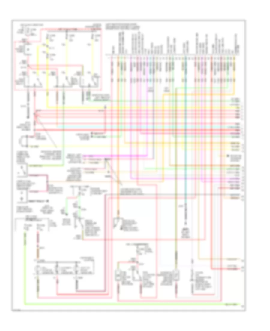
5.4L CNG, Engine Performance Wiring Diagrams (1 of 5) for Ford RV Cutaway E350 1998

List of elements for 5.4L CNG, Engine Performance Wiring Diagrams (1 of 5) for Ford RV Cutaway E350 1998:
- (behind upper left side of dash) g202
- (ends in harness)
- (eng ctrl harn, left rear of engine compt)
- (engine control harn, near breakout to fuel injector 1)
- (engine control harn, near breakout to mass air flow sensor)
- (engine control harn, right rear of eng compt near master cylinder)
- (front of left front fender)
- (front of right front fender)
- (left side of dash) (partial) data link connector
- A/c on sig
- Air conditioning system
- Aux pwr feed
- Ckp sens (+)
- Ckp sens (-)
- Data link (+)
- Data link (-)
- Digital transmission range sensor (dtr sensor) (left side of transmission)
- Dtr-tr1
- Dtr-tr2
- Dtr-tr4
- E4od ccs
- E4od ss1
- E4od ss2
- Ect
- Engine compartment fuse box (left front of engine compt)
- Feps (eprom)
- Fuel pump mon
- Fuse 10a
- Fuse 30a
- Fuse 5a
- G100
- G101
- Gnd
- Hot at all times
- Hot in run or start
- I/p fuse panel (behind left side of dash)
- Iat
- Ign coil 1
- Ign coil 3
- Ign coil 5
- Ign coil 6
- Ignition coils
- Inlet air ctrl
- Maf
- Mil
- Nca
- Not used
- O/d off
- Od off ind
- Ohms
- Pcm power diode
- Pcm power relay
- Powertrain control module (left side of engine compt, near brake master cylinder)
- Pwr gnd
- R n
- Radio capacitor no1 (upper left rear of engine)
- Radio capacitor no2 (right rear of engine)
- Red
- Rpm sens feed
- S110
- S127
- S140
- S142
- S156 (engine control harn, near breakout to coil per plug 6)
- S161
- S169
- S180
- S181
- S182
- S184
- S268
- Tcs
- Tft
- To dtr sensor (diagram 4 of 4)
- Transmission control indicator lamp
- Transmission control switch
- Vss (-)
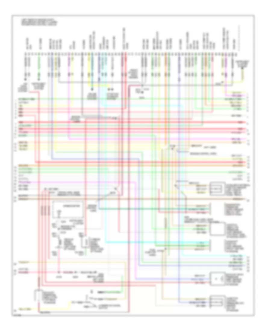
5.4L CNG, Engine Performance Wiring Diagrams (2 of 5) for Ford RV Cutaway E350 1998
List of elements for 5.4L CNG, Engine Performance Wiring Diagrams (2 of 5) for Ford RV Cutaway E350 1998:
- (behind left side of dash) g202
- (engine control harn, left rear of engine compt)
- (engine control harn, near breakout to 76-pin conn in left rear of engine compt) s126
- (engine control harn, near breakout to a/c cutout switch)
- (engine control harn, near breakout to coil per plug 9)
- (engine control harn, near breakout to pcm) s137
- (engine ctrl harn, near breakout to radio noise capacitor 1)
- (on lower intake manifold) instrumentation engine coolant temperature sensor
- (speedometer/ odometer) vehicle speed input
- C224
- C225
- Crankshaft position sensor (lower center front of engine)
- Engine compartment fuse box (left front of engine compt)
- Engine coolant temperature gauge
- Fuel guage input
- Fuel pump relay
- Fuel rail temperature sensor (on fuel rail, on right bank of engine)
- Fuse 30a
- G100 (front of left front fender)
- Hot at all times
- Injection pressure sensor (on fuel rail, on right bank of engine)
- Instrument cluster
- Intake air temperature sensor (center of engine compt, part of clean air tube)
- Malfunction indicator
- Not used
- Power
- Red
- Red/pnk
- S136
- S139
- S157
- S158
- S169
- S175
- Throttle position sensor (top of engine, near air intake)
5.4L CNG, Engine Performance Wiring Diagrams (3 of 5) for Ford RV Cutaway E350 1998
List of elements for 5.4L CNG, Engine Performance Wiring Diagrams (3 of 5) for Ford RV Cutaway E350 1998:
- (behind right kick panel) inertia fuel shut-off switch
- (behind upper left side of dash) g202
- (front of left front fender) g10o
- (front of right front fender) g101
- (fuel tank harn, under left center of vehicle)
- (right side of engine, on fuel rail)
- (transmission control harn, near breakout to dtr sensor)
- (transmission control harn, near breakout to transmission)
- (under left center of vehicle)
- Coast clutch solenoid
- E4od transmission
- Electronic pressure control solenoid
- Engine compartment fuse box (left front of engine compt)
- Forward aft-axle fuel tank
- Fuel rail cut-off valve
- Fuel tank sender
- Fuse 20a
- Hot at all times
- Midship fuel tank valve
- Ngv timer (left rear of engine compt)
- Rear aft-axle fuel tank
- Red
- Red/pnk
- S100
- S102
- S185 (engine ctrl harn, left rear of eng compt)
- S189
- S268
- S317
- S318
- S319
- S320
- Shift solenoid
- Starting/ charging system
- Torque converter clutch solenoid
- Transmission fluid temperature sensor
- Valve (near aft- axle fuel tank assy)
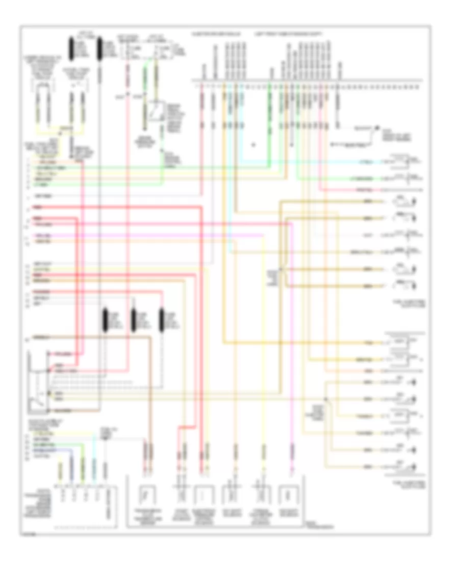
5.4L CNG, Engine Performance Wiring Diagrams (4 of 5) for Ford RV Cutaway E350 1998
List of elements for 5.4L CNG, Engine Performance Wiring Diagrams (4 of 5) for Ford RV Cutaway E350 1998:
- (eng ctrl harn, near breakout to e4od trans)
- (eng ctrl harn, near breakout to iat sensor)
- (engine ctrl harn, near breakout to coil plug 2)
- (front of left front fender)
- (fuel tank harn, near breakout to fuel tank temp sensor)
- (left front of engine)
- Data (+)
- Data (-)
- Fuel gauge
- Fuel injector
- Fuel press
- Fuel tank pressure sensor (under left center of vehicle, near fuel tank)
- Fuel tank temperature sensor (under left center of vehicle)
- Fuel temp
- G100
- Ground
- Ignition
- Inj no1 input
- Inj no1 out
- Inj no2 input
- Inj no2 out
- Inj no3 input
- Inj no3 out
- Inj no4 input
- Inj no4 out
- Inj no5 input
- Inj no5 out
- Inj no6 input
- Inj no6 out
- Inj no7 input
- Inj no7 out
- Inj no8 input
- Inj no8 out
- Inlet air control sensor
- Ngv module (on left rear of engine compt, near brake master cylinder)
- Power
- Red
- Red/pnk
- S155 (engine ctrl harn, near breakout to fuel injector 6)
- S159
- S160
- S181
- S188
- S316
- Sig return
- Tan
- Tan/ red
- Tan/red
- Timer
5.4L CNG, Engine Performance Wiring Diagrams (5 of 5) for Ford RV Cutaway E350 1998
List of elements for 5.4L CNG, Engine Performance Wiring Diagrams (5 of 5) for Ford RV Cutaway E350 1998:
- (behind upper left side of dash)
- (engine control harn, near breakout to a/c cutout switch)
- (front of left cylinder head) cylinder head temperature sensor
- (left side of transmission) vehicle speed sensor
- (near brake master cylinder) speed control servo/amplifier assembly
- 270 ohms
- 5v ref
- Brake on/off
- Brake pedal position switch
- Camshaft position sensor (on front of left cylinder head)
- Camshaft position sensor shield
- Cmp sensor
- Cyl head temp
- Digital transmission range sensor (dtr sensor) (left side of transmission)
- Dtr-tr3a
- Epc sol
- From dtr sensor (diagram 1 of 4)
- Fuel inj 1
- Fuel inj 2
- Fuel inj 3
- Fuel inj 4
- Fuel inj 5
- Fuel inj 6
- Fuel inj 7
- Fuel inj 8
- Fuel pump ctrl
- Fuel temp
- Fuse 15a
- G100 (front of left front fender)
- G101 (front of right front fender)
- G202
- Heated oxygen sensor (ho2s 11) (lower right rear of engine)
- Heated oxygen sensor (ho2s 21) (lower left rear of engine)
- Ho2s (11) htr
- Ho2s (21) htr
- Ho2s sig (11)
- Ho2s sig (21)
- Hot at all times
- I/p fuse panel (behind left side of dash)
- Idle air control valve (top center rear of engine, near air intake)
- Idle air ctrl
- Ign coil 2
- Ign coil 4
- Ign coil 7
- Ign coil 8
- Inj press
- Kap b(+)
- Maf sens in
- Mass air flow sensor (top center of engine)
- Nca
- Not used
- Powertrain control module (left rear of engine compt, near brake master cylinder)
- Pwr gnd
- Red
- Red/pnk
- S135
- S139
- S140
- S169
- S170
- S171
- Sig rtn
- Tan
- Tan/red
- Tcc sol
- Tp sens in
- Vpwr
- Vss (+)
- Vss input
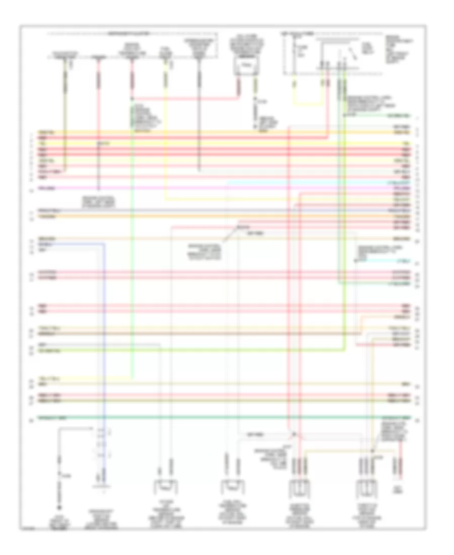
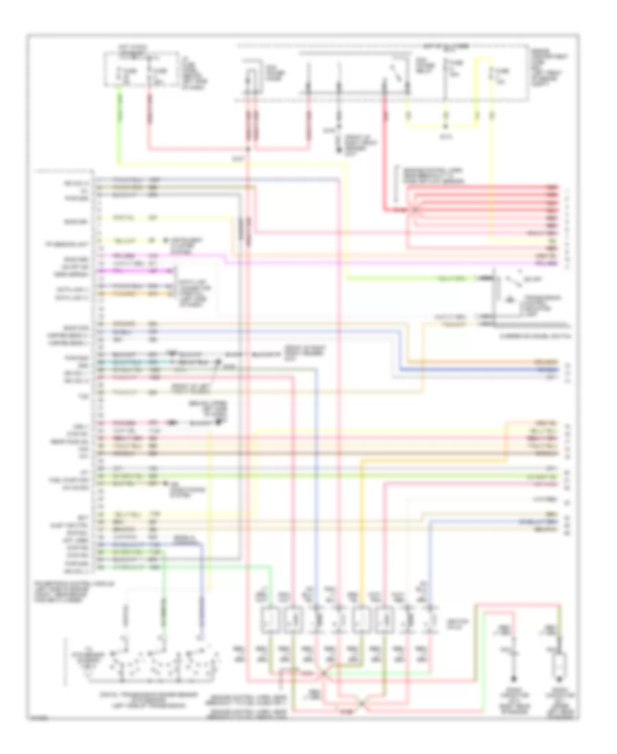
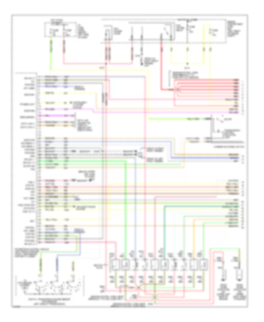
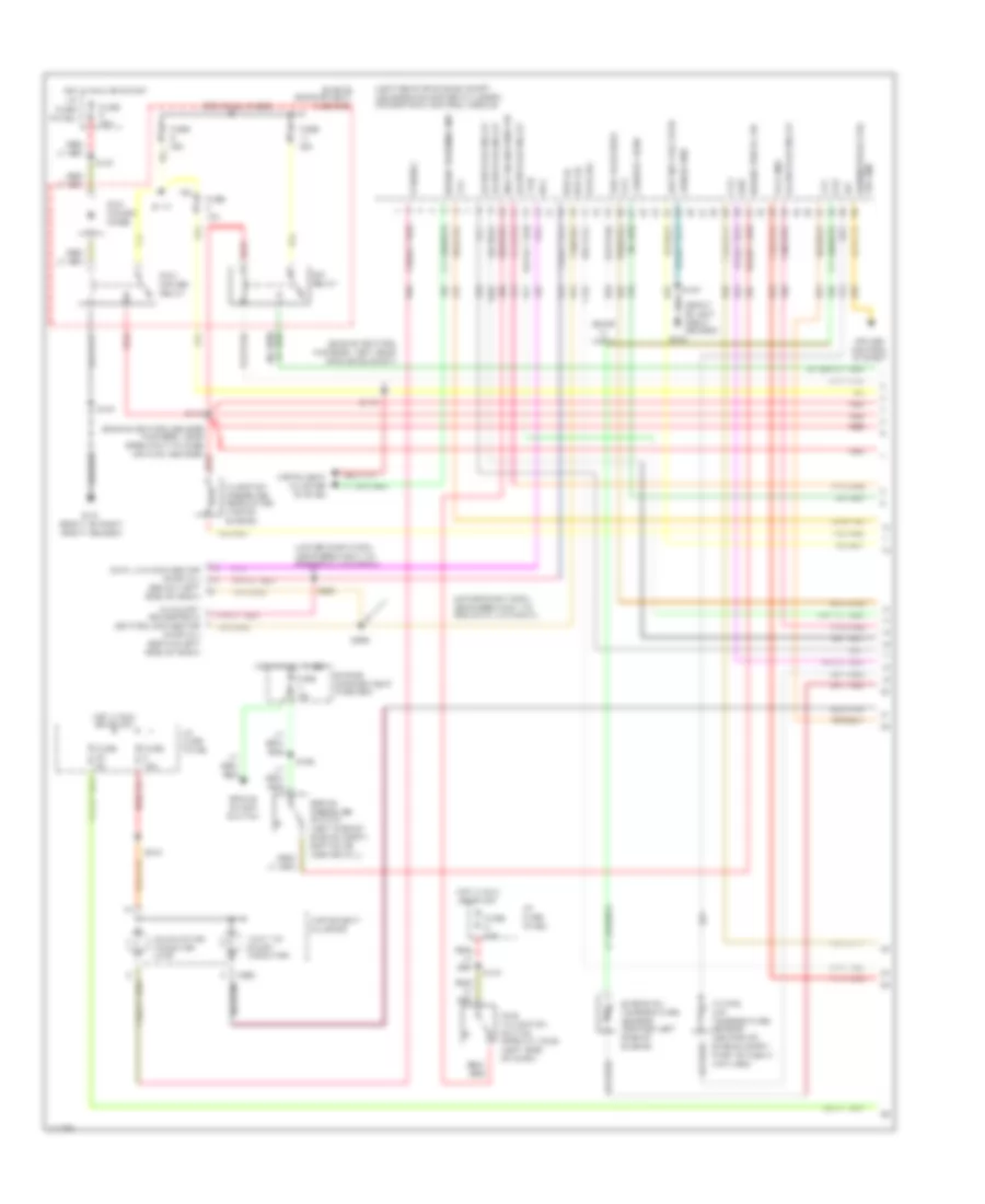
5.4L, Engine Performance Wiring Diagrams (1 of 4) for Ford RV Cutaway E350 1998
List of elements for 5.4L, Engine Performance Wiring Diagrams (1 of 4) for Ford RV Cutaway E350 1998:
- (behind upper left side of dash) g202
- (ends in harness)
- (engine control harn, near breakout to coil per plug 6)
- (engine control harn, near breakout to fuel injector 1)
- (engine control harn, near breakout to mass air flow sensor)
- (front of left front fender)
- (front of right front fender) g101
- A/c on sig
- Air conditioning system
- Data link (+)
- Data link (-)
- Data link connector (partial) (left side of dash)
- Digital transmission range sensor (dtr sensor) (left side of transmission)
- Dtr-tr1
- Dtr-tr2
- Dtr-tr4
- E4od ccs
- E4od ss1
- E4od ss2
- Ect
- Engine compartment fuse box (left front of engine compt)
- Evr sol
- Feps (eprom)
- Fp sending unit
- Fuel pump mon
- Fuse 10a
- Fuse 30a
- Fuse 5a
- G100
- Gnd
- Hot at all times
- Hot in run or start
- I/p fuse panel (behind left side of dash)
- Iat
- Ign coil 1
- Ign coil 3
- Ign coil 5
- Ign coil 6
- Ignition coils
- Inlet air ctrl
- Instrument cluster system
- Maf
- Mil
- Misfire sens (+)
- Misfire sens (-)
- Nca
- Not used
- O/d off
- Od off ind
- Overdrive cancel switch
- Pcm power diode
- Pcm power relay
- Powertrain control module (left side of engine compt, near brake master cylinder)
- Pwr gnd
- R n
- Radio capacitor no 1 (upper left rear of engine
- Radio capacitor no 2 (right rear of engine)
- Rear ho2s (22)
- Red
- S110
- S127
- S140
- S142
- S156
- S161
- S169
- S181
- S268
- Tcs
- Tft
- To dtr sensor (diagram 4 of 4)
- Transmission control indicator lamp
- Vss (-)
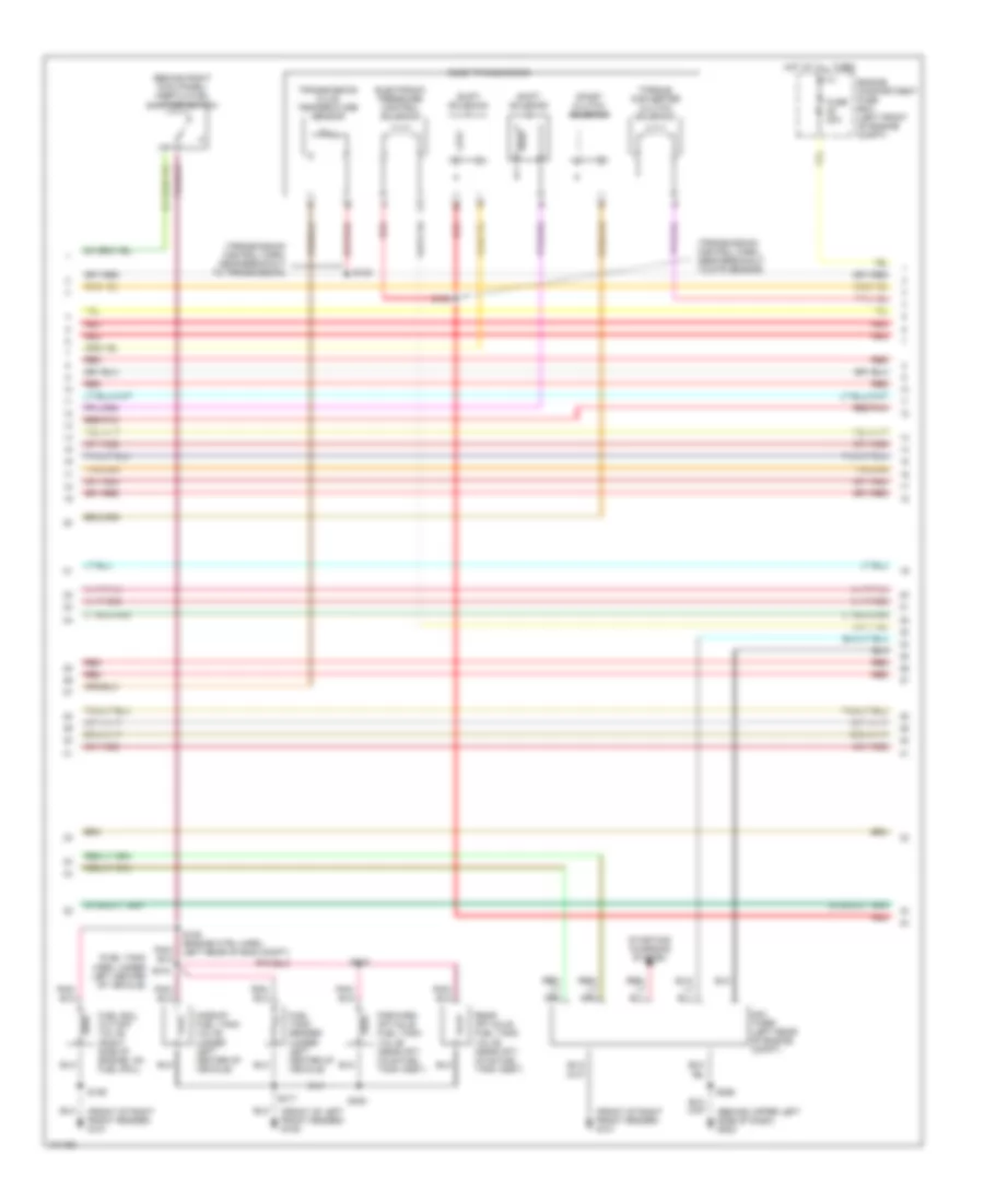
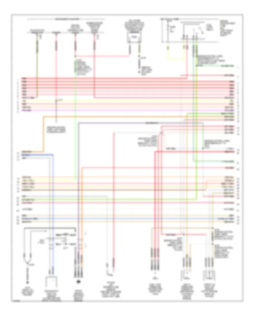
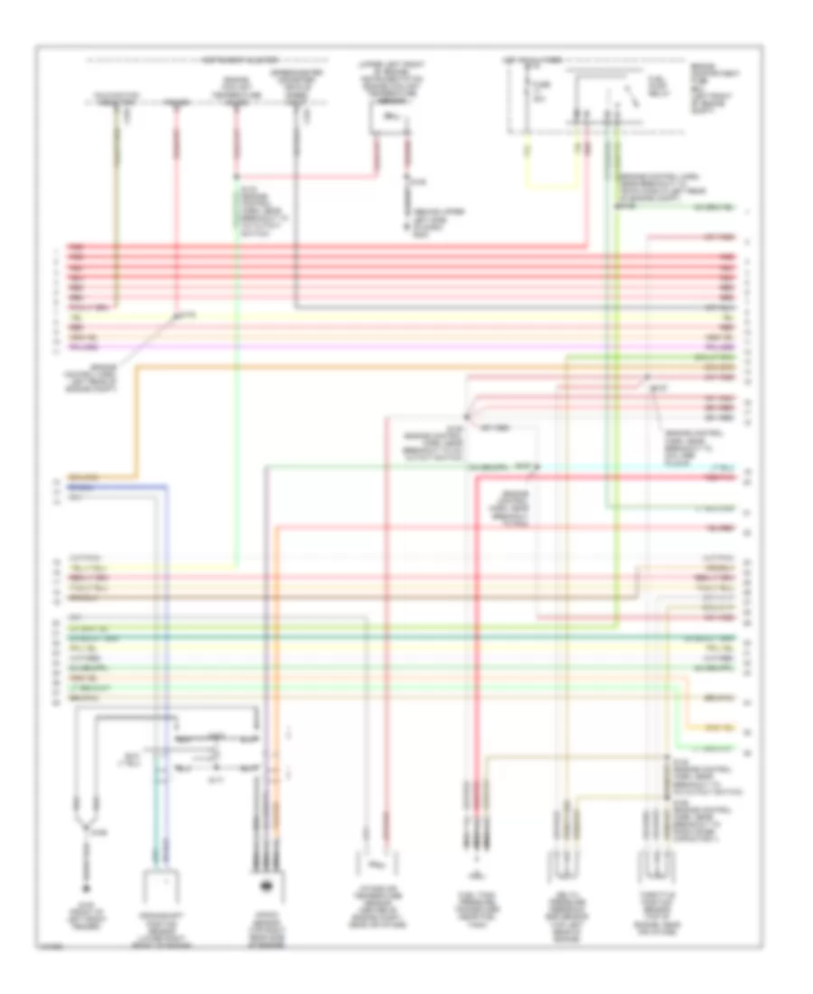
5.4L, Engine Performance Wiring Diagrams (2 of 4) for Ford RV Cutaway E350 1998
List of elements for 5.4L, Engine Performance Wiring Diagrams (2 of 4) for Ford RV Cutaway E350 1998:
- (behind left side of dash) g202
- (engine control harn, left rear of engine compt)
- (engine control harn, near breakout to 76-pin conn in left rear of engine compt) s126
- (engine control harn, near breakout to pcm) s137
- (on lower intake manifold) instrumentation engine coolant temperature sensor
- (speedometer/ odometer) vehicle speed input
- C224
- C225
- Crankshaft position sensor (lower center front of engine)
- Delta pressure feedback egr sensor (top right side of engine)
- Engine compartment fuse box (left front of engine compt)
- Engine coolant temperature gauge
- Fuel pump relay
- Fuel tank pressure transducer (near fuel tank)
- Fuse 30a
- G100 (front of left front fender)
- Hot at all times
- Instrument cluster
- Intake air temperature sensor (center of engine compt, part of clean air tube)
- Knock sensor (top right rear of engine)
- Malfunction indicator
- Nca
- Power
- Red
- Red/pnk
- S136 (engine control harn, near breakout to a/c cutout switch)
- S138 (engine control harn, near breakout to a/c cutout switch)
- S139
- S157 (engine control harn, near breakout to coil per plug 9)
- S158 (engine control harn, near breakout to radio noise capacitor 1)
- S169
- S170
- S171
- S175
- Throttle position sensor (top of engine, near air intake)
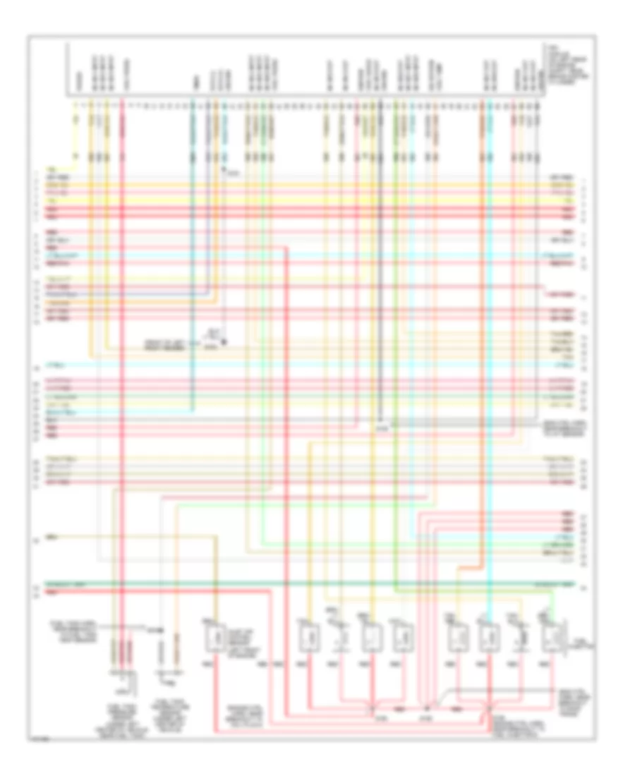
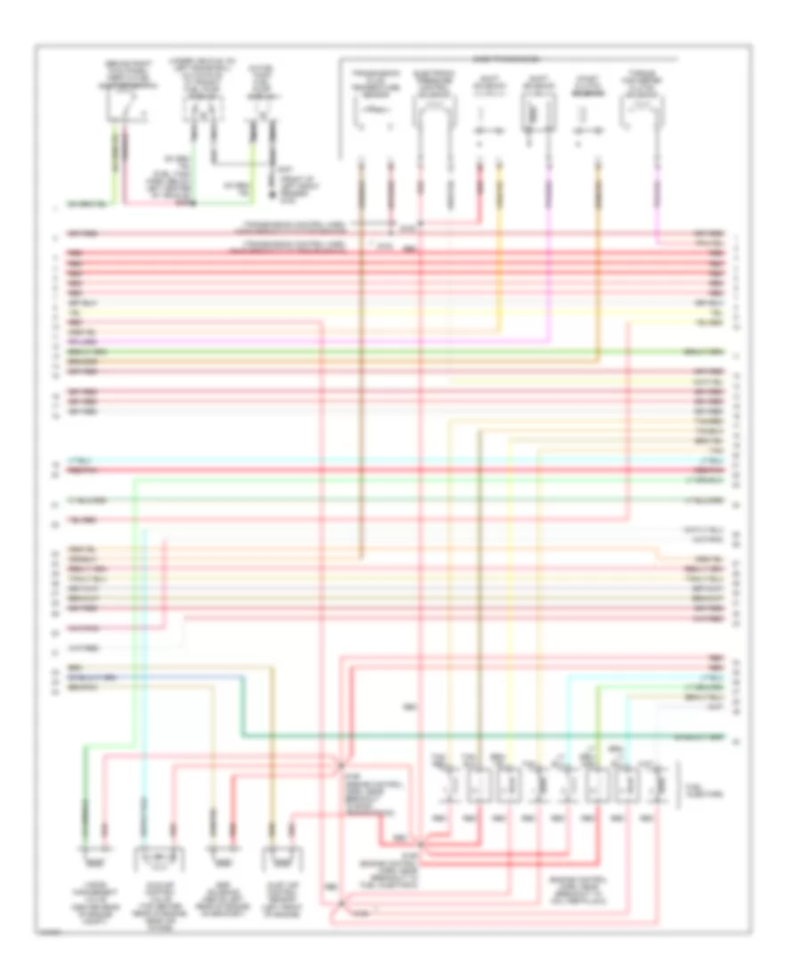
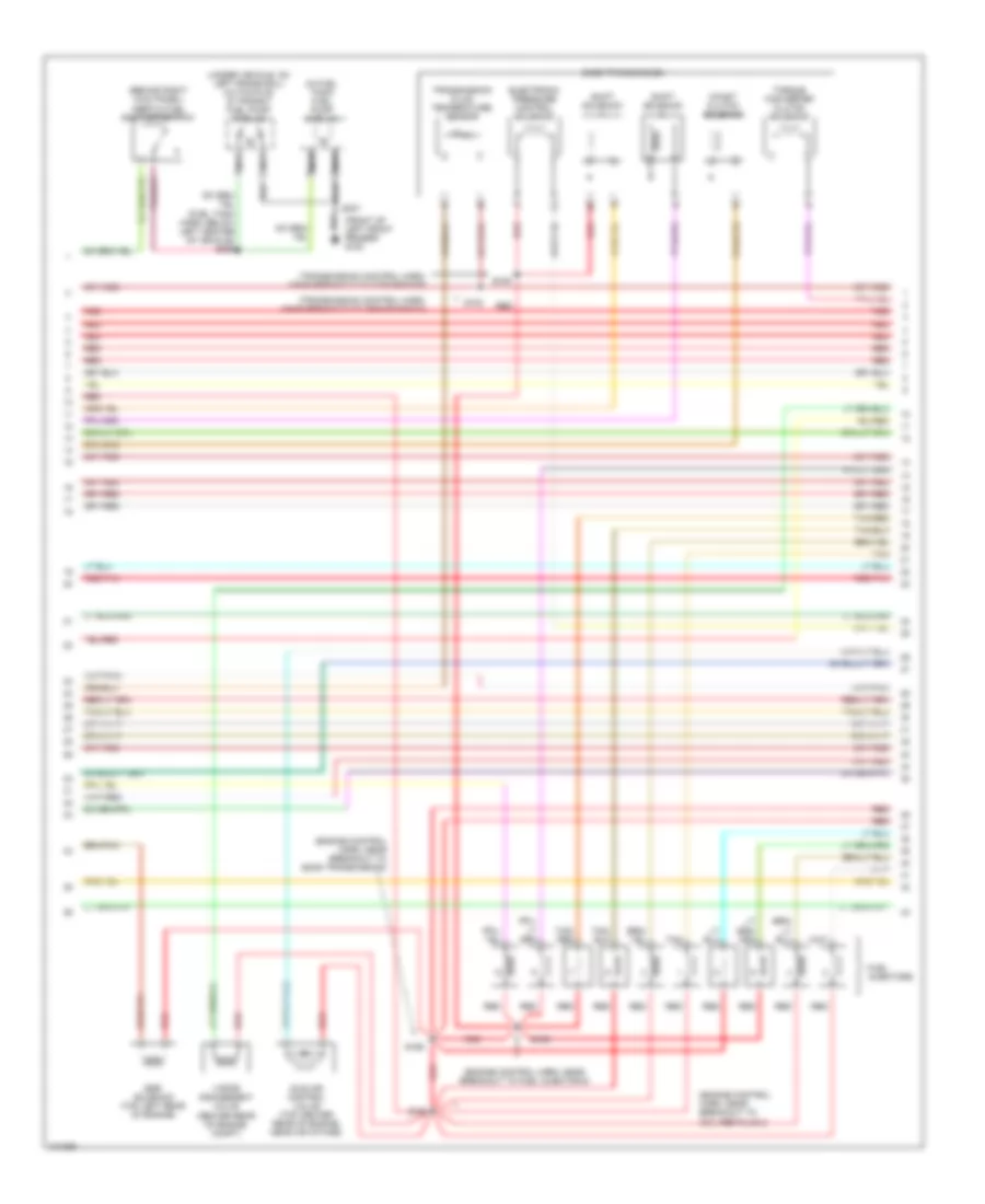
5.4L, Engine Performance Wiring Diagrams (3 of 4) for Ford RV Cutaway E350 1998
List of elements for 5.4L, Engine Performance Wiring Diagrams (3 of 4) for Ford RV Cutaway E350 1998:
- (behind right kick panel) inertia fuel shut-off switch
- (center rear of engine compt)
- (engine control harn, near breakout to coil per plug 2)
- (front of left front fender) g100
- (fuel tank harn, below left center of vehicle) s309
- (in fuel tank) fuel pump module
- (left front of engine)
- (transmission control harn, near breakout to dtr sensor)
- (transmission control harn, near breakout to transmission)
- (under vehicle, on left frame rail) (cutaways) in transit fuel pump module
- Coast clutch solenoid
- E4od transmission
- Egr solenoid (above left rear of engine, on bracket)
- Electronic pressure control solenoid
- Fuel injectors
- Idle air control valve (top center rear of engine, near air intake)
- Inlet air control sensor
- Nca
- Red
- Red/pnk
- S100
- S102
- S155 (engine control harn, near breakout to fuel injector 6)
- S159 (engine control, harn, near breakout to e4od transmission)
- S160
- S307
- Shift solenoid
- Tan
- Tan/ red
- Tan/red
- Torque converter clutch solenoid
- Transmission fluid temperature sensor
- Vapor management valve
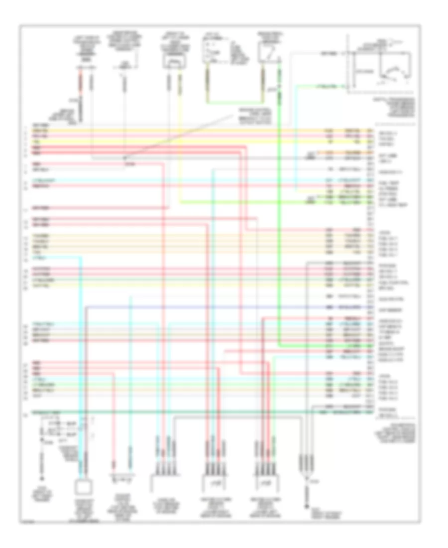
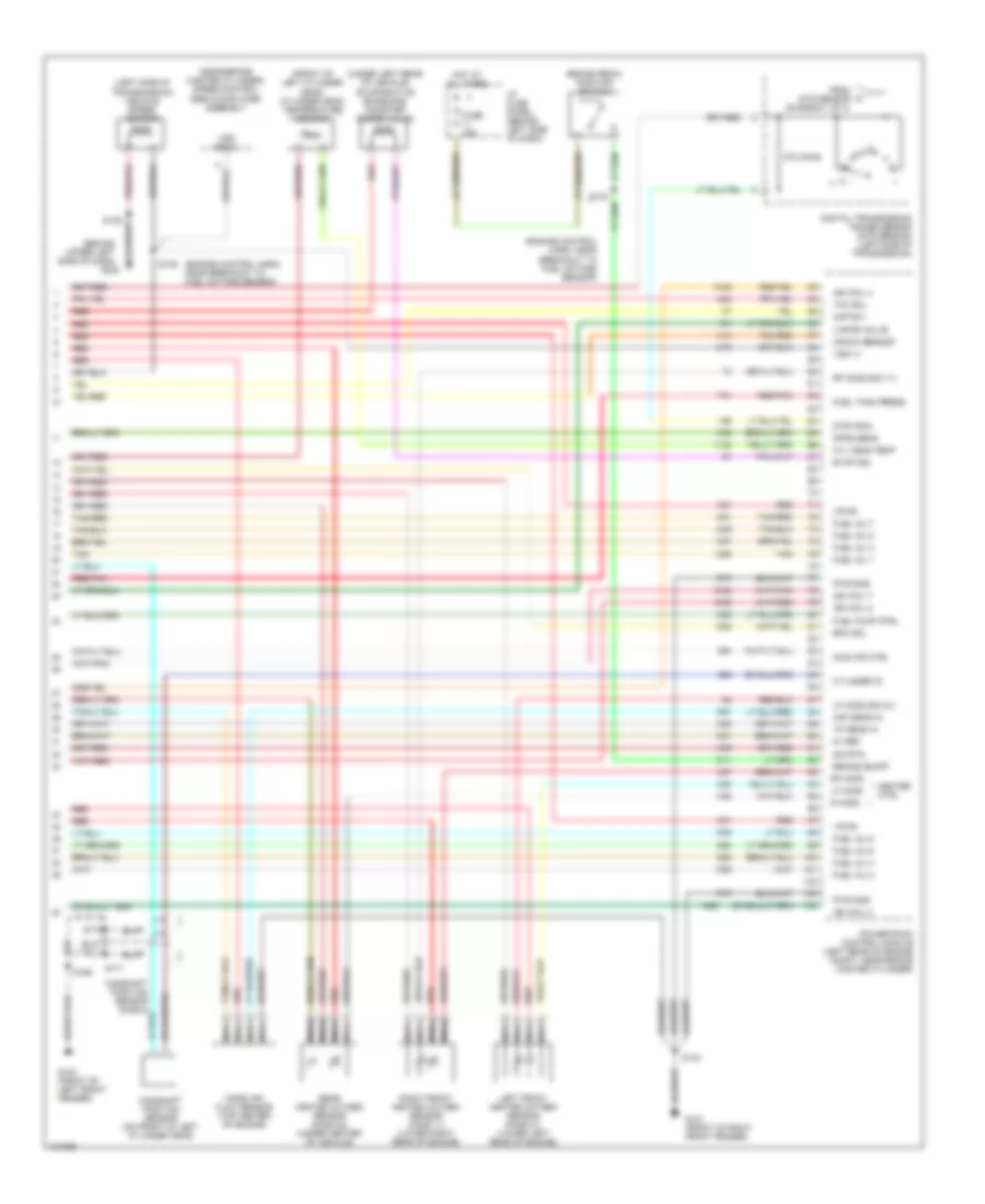
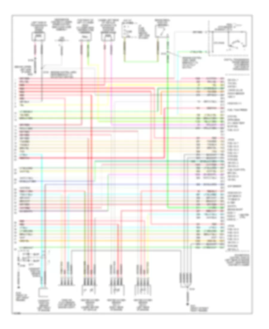
5.4L, Engine Performance Wiring Diagrams (4 of 4) for Ford RV Cutaway E350 1998
List of elements for 5.4L, Engine Performance Wiring Diagrams (4 of 4) for Ford RV Cutaway E350 1998:
- (behind upper left side of dash)
- (engine control harn, near breakout to fuel octane sensor)
- (front of left cylinder head) cylinder head temperature sensor
- (left side of transmission) vehicle speed sensor
- (near brake master cylinder) speed control servo/amplifier assembly
- (under left rear of vehicle) evaporative emissions canister purge valve
- 270 ohms
- 5v ref
- Brake on/off
- Brake pedal position switch
- Camshaft position sensor (on front of left cylinder head)
- Camshaft position sensor shield
- Cyl head temp
- Cylinder id
- Digital transmission range sensor (dtr sensor) (left side of transmission)
- Dpfe sens
- Dtr-tr3a
- Epc sol
- Evap sol
- From dtr sensor (diagram 1 of 4)
- Fuel inj 1
- Fuel inj 2
- Fuel inj 3
- Fuel inj 4
- Fuel inj 5
- Fuel inj 6
- Fuel inj 7
- Fuel inj 8
- Fuel pump ctrl
- Fuel tank press
- Fuse 15a
- G100 (front of left front fender)
- G101 (front of right front fender)
- G202
- Heater ctrl
- Hot at all times
- I/p fuse panel (behind left side of dash)
- Idle air ctrl
- Ign coil 2
- Ign coil 4
- Ign coil 7
- Ign coil 8
- Kap b(+)
- Knock sensor
- Left front heated oxygen sensor (ho2s 21) (lower left rear of engine)
- Lf ho2s
- Lf ho2s sig (21)
- Maf sens in
- Mass air flow sensor (top center of engine)
- Nca
- Powertrain control module (left rear of engine compt, near brake master cylinder)
- Pwr gnd
- R ho2s
- Rear heated oxygen sensor (ho2s 22) (under center of vehicle)
- Red
- Red/pnk
- Rf ho2s
- Rf ho2s sig (11)
- Right front heated oxygen sensor (ho2s 11) (lower right rear of engine)
- S135
- S139
- S140
- S169
- S170
- S171
- Sig rtn
- Tan
- Tan/red
- Tcc sol
- Tp sens in
- Vapor valve
- Vpwr
- Vss (+)
- Vss input
6.8L
6.8L, Engine Performance Wiring Diagrams (1 of 4) for Ford RV Cutaway E350 1998
List of elements for 6.8L, Engine Performance Wiring Diagrams (1 of 4) for Ford RV Cutaway E350 1998:
- (behind upper left side of dash)
- (ends in harness)
- (engine control harn, near breakout to fuel injector 1)
- (engine control harn, near breakout to fuel injector 6)
- (engine control harn, near breakout to mass air flow sensor)
- (front of left front fender)
- (front of right front fender)
- (front of right front fender) g101
- A/c on sig
- Air conditioning system
- Ckp sens (+)
- Ckp sens (-)
- Data link (+)
- Data link (-)
- Data link connector (partial) (behind left side of dash)
- Digital transmission range sensor (dtr sensor) (left side of transmission)
- Dtr-tr1
- Dtr-tr2
- Dtr-tr4
- E4od ccs
- E4od ss1
- E4od ss2
- Ect
- Engine compartment fuse box (left front of engine compt)
- Evr sol
- Feps (eprom)
- Fp send unit
- Fuel inj 10
- Fuel pump mon
- Fuse 10a
- Fuse 30a
- Fuse 5a
- G100
- G101
- G202
- Gnd
- Ho2s (22)
- Hot at all times
- Hot in run or start
- I/p fuse panel (behind left side of dash)
- Iat
- Ign coil 1
- Ign coil 10
- Ign coil 5
- Ign coil 6
- Ignition coils
- Instrument cluster system
- Maf
- Mil
- Nca
- Not used
- O/d off
- Od off ind
- Overdrive cancel switch
- Pcm power diode
- Pcm power relay
- Powertrain control module (left rear of engine compt, near brake master cylinder)
- Pwr gnd
- R n
- Radio noise capacitor no1 (upper left rear of engine)
- Radio noise capacitor no2 (upper right rear of engine)
- Red
- S110
- S127
- S140
- S142
- S161
- S162
- S169
- S268
- Tcs
- Tft
- To dtr sensor (diagram 4 of 4)
- Transmission control indicator lamp
- Vss (-)
6.8L, Engine Performance Wiring Diagrams (2 of 4) for Ford RV Cutaway E350 1998
List of elements for 6.8L, Engine Performance Wiring Diagrams (2 of 4) for Ford RV Cutaway E350 1998:
- (behind upper left side of dash) g202
- (engine control harn, left rear of engine compt)
- (engine control harn, near breakout to 76-pin conn in left rear of engine compt) s126
- (engine control harn, near breakout to coil per plug 9)
- (engine control harn, near breakout to pcm)
- (speedometer/ odometer) vehicle speed input
- (upper left front of engine) instrumentation engine coolant temperature sensor
- C224
- C225
- Crankshaft position sensor (lower right front of engine)
- Delta pressure feedback egr sensor (top left rear of engine)
- Engine compartment fuse box (left front of engine compt)
- Engine coolant temperature gauge
- Fuel pump relay
- Fuel tank pressure transducer (near fuel tank)
- Fuse 30a
- G100 (front of left front fender)
- Hot at all times
- Instrument cluster
- Intake air temperature sensor (center of engine compt, near air intake)
- Knock sensor (top right rear side of engine)
- Malfunction indicator
- Nca
- Power
- Red
- Red/pnk
- S136 (engine control harn, near breakout to a/c cutout switch)
- S137
- S138 (engine control harn, near breakout to a/c cutout switch)
- S157
- S158 (engine control harn, near breakout to radio noise capacitor 1)
- S169
- S170
- S171
- S175
- Throttle position sensor (top of engine, near air intake)
6.8L, Engine Performance Wiring Diagrams (3 of 4) for Ford RV Cutaway E350 1998
List of elements for 6.8L, Engine Performance Wiring Diagrams (3 of 4) for Ford RV Cutaway E350 1998:
- (behind right kick panel) inertia fuel shut-off switch
- (center rear of engine compt)
- (engine control harn, near breakout to coil per plug 2)
- (engine control harn, near breakout to e4od transmission)
- (engine control harn, near breakout to fuel injector 6)
- (front of left front fender) g100
- (fuel tank harn, below left center of vehicle) s309
- (in fuel tank) fuel pump module
- (transmission control harn, near breakout to dtr sensor)
- (transmission control harn, near breakout to transmission)
- (under vehicle, on left frame rail) (cutaways) in transit fuel pump module
- Coast clutch solenoid
- E4od transmission
- Egr solenoid (top left rear of engine)
- Electronic pressure control solenoid
- Fuel injectors
- Idle air control valve (top center rear of engine, near air intake)
- Nca
- Red
- Red/pnk
- S100
- S102
- S155
- S159
- S160
- S307
- Shift solenoid
- Tan
- Tan/ red
- Tan/red
- Torque converter clutch solenoid
- Transmission fluid temperature sensor
- Vapor management valve
6.8L, Engine Performance Wiring Diagrams (4 of 4) for Ford RV Cutaway E350 1998
List of elements for 6.8L, Engine Performance Wiring Diagrams (4 of 4) for Ford RV Cutaway E350 1998:
- (behind upper left side of dash)
- (engine control harn, near breakout to a/c cutout switch)
- (left side of transmission) vehicle speed sensor
- (near brake master cylinder) speed control servo/amplifier assembly
- (top front of left cylinder head) cylinder head temperature sensor
- (under left rear of vehicle) evaporative emissions canister purge valve
- 270 ohms
- 5v ref
- Brake on/off
- Brake pedal position switch
- Camshaft position sensor (left front of engine)
- Camshaft position sensor shield
- Cmp sensor
- Cyl head temp
- Digital transmission range sensor (dtr sensor) (left side of transmission)
- Dpfe sens
- Dtr-tr3
- Epc sol
- Evap sol
- From dtr sensor (diagram 1 of 4)
- Fuel inj 1
- Fuel inj 2
- Fuel inj 3
- Fuel inj 4
- Fuel inj 5
- Fuel inj 6
- Fuel inj 7
- Fuel inj 8
- Fuel inj 9
- Fuel pump ctrl
- Fuel tank press
- Fuse 15a
- G100 (front of left front fender)
- G101 (front of right front fender)
- G202
- Heated oxygen sensor (no 11) (right rear of engine)
- Heated oxygen sensor (no 21) (left rear of engine)
- Heated oxygen sensor (no 22) (under center of vehicle)
- Heater ctrl
- Ho2s 11
- Ho2s 21
- Ho2s 22
- Ho2s sig (11)
- Ho2s sig (21)
- Hot at all times
- I/p fuse panel (behind left side of dash)
- Iac sol
- Ign coil 2
- Ign coil 3
- Ign coil 4
- Ign coil 7
- Ign coil 8
- Ign coil 9
- Kap b(+)
- Knock sensor
- Maf sens in
- Mass air flow sensor (top center of engine compt)
- Nca
- Powertrain control module (left rear of engine compt, near brake master cylinder)
- Pwr gnd
- Red
- Red/pnk
- S135
- S139
- S140
- S169
- S170
- S171
- Sig rtn
- Tan
- Tan/red
- Tcc sol
- Tp sens in
- Vapor valve
- Vpwr
- Vss (+)
- Vss input
7.3L
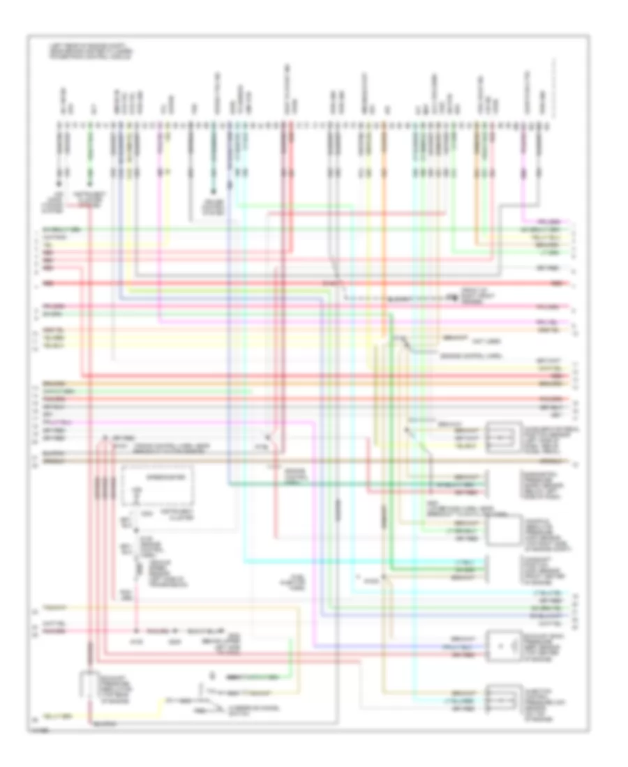
7.3L DI Turbo Diesel, Engine Performance Wiring Diagrams, with Electric Fuel Pump (1 of 3) for Ford RV Cutaway E350 1998
List of elements for 7.3L DI Turbo Diesel, Engine Performance Wiring Diagrams, with Electric Fuel Pump (1 of 3) for Ford RV Cutaway E350 1998:
- (below left side of dash) data link connector
- (eng ctrl harn, left rear of engine compt)
- (eng ctrl sensor harness, near breakout to mass air flow sensor)
- (left rear of engine compt, near brake master cylinder) powertrain control module
- (lower dash harn, near breakout to rke data link conn)
- App sens
- Aux tach feed
- Auxiliary powertrain control connector (behind left side of dash)
- Brake on/off switch
- Brake press sw
- Brake pressure switch (left side of engine compt, bottom of master cyl)
- Brake warning ind
- Bus (+)
- Bus (-)
- C225
- C226
- Cam pos sens
- Ccs sol
- Dlc
- Driveline disconn
- Driveline disconnect switch (behind left side of dash)
- Dtr-tr1
- Ebp sens
- Engine compartment fuse box
- Engine oil temperature sensor (center left side of engine)
- Eot
- Fuel line heater (top center of engine)
- Fuel line htr
- Fuel pump (left rear of engine compt)
- Fuel pump relay
- Fuse 10a
- Fuse 15a
- Fuse 30a
- Fuse 5a
- G100 (front of left front fender)
- G101 (front of right front fender)
- Gen pwr sw
- Glow plug relay
- Horn/speed ctrl sw gnd
- Hot at all times
- Hot in run or start
- I/p fuse panel
- Iat
- Idle validation sw
- Idle validation switch (open at idle) (left side of dash)
- Idm relay
- Inertia fuel shutoff switch (behind right kick panel)
- Injection pressure regulator (top of engine)
- Instrument cluster
- Instrument cluster system
- Intake air temperature sensor (center of engine compt, part of clean air tube)
- Mal- function indicator
- Mil dlc
- Not used
- Pcm power diode
- Pcm power relay
- Red
- S110
- S127
- S129
- S140
- S142
- S142 (fuel inj harness)
- S167
- S175
- S176
- S180 (engine ctrl harn, above master cyl)
- S213
- S262
- S263
- Shield gnd
- Ss1
- Starting/ charging system
- Tcil
- Tcs sens
- Tft
- Vss gnd
- Wait to start indicator
- Water in fuel ind
- Water in fuel indicator
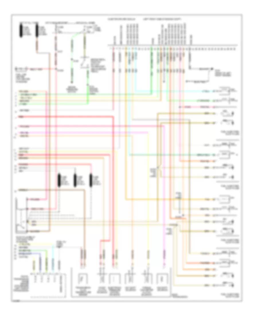
7.3L DI Turbo Diesel, Engine Performance Wiring Diagrams, with Electric Fuel Pump (2 of 3) for Ford RV Cutaway E350 1998
List of elements for 7.3L DI Turbo Diesel, Engine Performance Wiring Diagrams, with Electric Fuel Pump (2 of 3) for Ford RV Cutaway E350 1998:
- (engine control harn)
- (engine ctrl harness)
- (front of right front fender)
- (fuel injector harn)
- (left rear of engine compt, near brake master cylinder) powertrain control module
- (not used)
- (trans harn, near breakout to dtrs)
- A/c on sig
- Accelerator pedal position sensor (left side of dash, above accel pedal)
- Accl pos sens
- Air cond- itioning system
- Baro
- Barometric pressure (baro) sensor (below left side of dash)
- Boo sw
- C224
- Camshaft position (cmp) sensor (front center of engine)
- Charge ind
- Cid sig
- Cmp rtn
- Cruise control system
- Dtr-tr2
- Dtr-tr4
- Ect sens
- Epc sol
- Epr
- Exhaust back pressure (ebp) sensor (top center of engine)
- Exhaust pressure regulator (top rear of engine)
- Fuel deliv sig
- Fuel pump rly
- Fuel pump sender
- G101
- G202 (behind upper left side of dash)
- Gen pwr sw
- Glow plug ctrl
- Icp sens
- Idm enable out
- Idm sig in
- Injection control pressure (icp) sensor (on top of engine)
- Instrument cluster
- Instrument cluster system
- Ipr sens
- Kapwr
- Manifold absolute pressure (map) sensor (top right side of engine compt)
- Map sens
- Nca
- Overdrive cancel switch
- Pwr gnd
- Red
- S1001
- S1002
- S120
- S135
- S136
- S137
- S138
- S139
- S140
- S205
- S261 (lower dash harn, near breakout to data link conn)
- Sig rtn
- Speed ctrl sig
- Speedometer
- Starting/ charging system
- Tcc
- Tcil
- Tcs
- Tr sensor
- Tss sens
- Turbine shaft speed sensor (right side of trans)
- Vehicle speed sensor (left side of trans)
- Vpwr
- Vref
- Vs sens
- Vss in
- Wait to start ind
7.3L DI Turbo Diesel, Engine Performance Wiring Diagrams, with Electric Fuel Pump (3 of 3) for Ford RV Cutaway E350 1998
List of elements for 7.3L DI Turbo Diesel, Engine Performance Wiring Diagrams, with Electric Fuel Pump (3 of 3) for Ford RV Cutaway E350 1998:
- (behind left side of dash) g202
- (fuel inj harn) s1007
- (in fuel tank) fuel pump module
- (left front side of engine compt)
- (under vehicle, on left frame rail) (cutaways) in transit fuel pump module
- Brake pedal position switch (above brake pedal)
- Brake pressure switch
- Cid sig in
- Coast clutch solenoid
- Digital transmission range sensor (dtr sensor) (left side of transmission)
- E4od transmission
- Electronic pressure control solenoid
- Fuel delivery sig
- Fuel inj feed left
- Fuel inj feed right
- Fuel injector no1
- Fuel injector no2
- Fuel injector no3
- Fuel injector no4
- Fuel injector no5
- Fuel injector no6
- Fuel injector no7
- Fuel injector no8
- Fuel injectors/ glow plugs
- Fuse 15a
- Fuse 30a
- G100 (front of left front fender)
- Glow plug relay (top right side of engine)
- Hot at all times
- Hot in run or start
- I/p fuse panel
- Idm feedback sig
- Inj shield gnd
- Injector driver module
- Nca
- No1
- No1 shift solenoid
- No2
- No2 shift solenoid
- No3
- No4
- No5
- No6
- No7
- No8
- P, 2, 1
- P, n, 1
- P, r, 2
- P, r, n
- Pwr gnd
- Red
- S1003 (fuel injector harn)
- S1004 (fuel inj harn)
- S127
- S129
- S134 (engine control harn)
- S308
- S310 (fuel tank harn, below left frt of vehicle)
- Sig rtn
- Signal return
- Tan
- Tan/red
- Torque converter clutch solenoid
- Transmission fluid temperature sensor
- Vpwr
7.3L DI Turbo Diesel, Engine Performance Wiring Diagrams, without Electric Fuel Pump (1 of 3) for Ford RV Cutaway E350 1998
List of elements for 7.3L DI Turbo Diesel, Engine Performance Wiring Diagrams, without Electric Fuel Pump (1 of 3) for Ford RV Cutaway E350 1998:
- "wait to start" indicator
- (ends in harn)
- (engine control harness, left rear of engine compt)
- (engine control sensor harness, near breakout to mass air flow sensor)
- (front of left front fender)
- (left rear of engine compt, near brake master cylinder) powertrain control module
- (lower dash harn, near breakout to rke data link conn)
- App ref volt rtn
- Aux tach feed
- Auxiliary powertrain control connector (partial) (behind left side of dash)
- Brake on/off switch
- Brake press sw
- Brake pressure switch (left side of engine compt, bottom of master cyl)
- Brake warning ind
- Bus (+)
- Bus (-)
- C225
- Cam pos sens
- Ccs
- Cruise control system
- Data link connector (partial) (below left side of dash)
- Dlc
- Dtr-tr1
- Ebp
- Engine compartment fuse box
- Engine oil temperature sensor (center left side of engine)
- Eot
- Fuse 10a
- Fuse 15a
- Fuse 30a
- Fuse 5a
- G100
- G101 (front of right front fender)
- Glow plug relay
- Hot at all times
- Hot in run or start
- I/p fuse panel
- Iat
- Idle validation sw
- Idle validation switch (open at idle) (left side of dash)
- Idm relay
- Injection pressure regulator (top of engine)
- Instrument cluster
- Instrument cluster system
- Intake air temperature sensor (center of engine compt, part of clean air tube)
- Malfunction indicator lamp
- Pcm dlc
- Pcm power diode
- Pcm power relay
- Red
- S110
- S127
- S129
- S140
- S142
- S167
- S175
- S213
- S262
- S263
- Shield gnd
- Ss1
- Sw gnd horn/speed ctrl
- Tcil
- Tcs
- Tft
- Vss gnd
7.3L DI Turbo Diesel, Engine Performance Wiring Diagrams, without Electric Fuel Pump (2 of 3) for Ford RV Cutaway E350 1998
List of elements for 7.3L DI Turbo Diesel, Engine Performance Wiring Diagrams, without Electric Fuel Pump (2 of 3) for Ford RV Cutaway E350 1998:
- (engine control harn)
- (front of right front fender)
- (fuel injector harn)
- (left rear of engine compt, near brake master cylinder) powertrain control module
- (not used)
- (trans control harn, near breakout to dtr sensor)
- A/c on sig
- Accelerator pedal position sensor (left side of dash, above accel pedal)
- Accl pos sens
- Air cond- itioning system
- Baro
- Barometric pressure (baro) sensor (below left side of dash)
- Boo
- C224
- Camshaft position (cmp) sensor (front center of engine)
- Cid sig
- Cmp rtn
- Cruise control system
- Dtr-tr2
- Dtr-tr4
- Ect
- Epc
- Epr
- Exhaust back pressure (ebp) sensor (top center of engine)
- Exhaust pressure regulator (top rear of engine)
- Fuel deliv sig
- G101
- G202 (behind upper left side of dash)
- Glow plug ctrl
- Icp
- Idm enable out
- Idm sig in
- Injection control pressure (icp) sensor (on top of engine)
- Instrument cluster
- Instrument cluster system
- Ipr
- Kapwr
- Manifold absolute pressure (map) sensor (top right side of engine compt)
- Map
- Nca
- Overdrive cancel switch
- Pwr gnd
- Red
- S1001
- S1002
- S135 (engine control harn)
- S136
- S138
- S139
- S140
- S205
- S261 (lower dash harn, near breakout to data link conn)
- Sig rtn
- Speed ctrl sig
- Speedometer
- Tcc
- Tcil
- Tcs
- Tr sensor
- Vehicle speed sensor (left side of transmission)
- Vpwr
- Vref
- Vss
- Vss in
- Wait to start ind
7.3L DI Turbo Diesel, Engine Performance Wiring Diagrams, without Electric Fuel Pump (3 of 3) for Ford RV Cutaway E350 1998
List of elements for 7.3L DI Turbo Diesel, Engine Performance Wiring Diagrams, without Electric Fuel Pump (3 of 3) for Ford RV Cutaway E350 1998:
- (fuel inj harn)
- (fuel inj harn) s1007
- (left front side of engine compt)
- Brake pedal position switch (on bracket, above brake pedal)
- Brake pressure switch
- Cid sig in
- Coast clutch solenoid
- Digital transmission range sensor (dtr sensor) (left side of transmission)
- E4od transmission
- Electronic pressure control solenoid
- Fuel delivery sig
- Fuel inj feed left
- Fuel inj feed right
- Fuel injector no1
- Fuel injector no2
- Fuel injector no3
- Fuel injector no4
- Fuel injector no5
- Fuel injector no6
- Fuel injector no7
- Fuel injector no8
- Fuel injectors/ glow plugs
- Fuel line heater (top center of engine)
- Fuse 15a
- Fuse 30a
- G100 (front of left front fender)
- Glow plug relay (top right side of engine)
- Hot at all times
- Hot in run or start
- I/p fuse panel
- Idm feedback sig
- Inj shield gnd
- Injector driver module
- Nca
- No1
- No1 shift solenoid
- No2
- No2 shift solenoid
- No3
- No4
- No5
- No6
- No7
- No8
- P, 2, 1
- P, n, 1
- P, r, 2
- P, r, n
- Pwr gnd
- Red
- S1000
- S1003
- S1004 (fuel inj harn)
- S1005
- S1006
- S127
- S129
- S134 (engine control harn)
- Sig rtn
- Signal return
- Tan
- Tan/red
- Torque converter clutch solenoid
- Transmission fluid temperature sensor
- Vpwr