ENGINE PERFORMANCE
3.0L
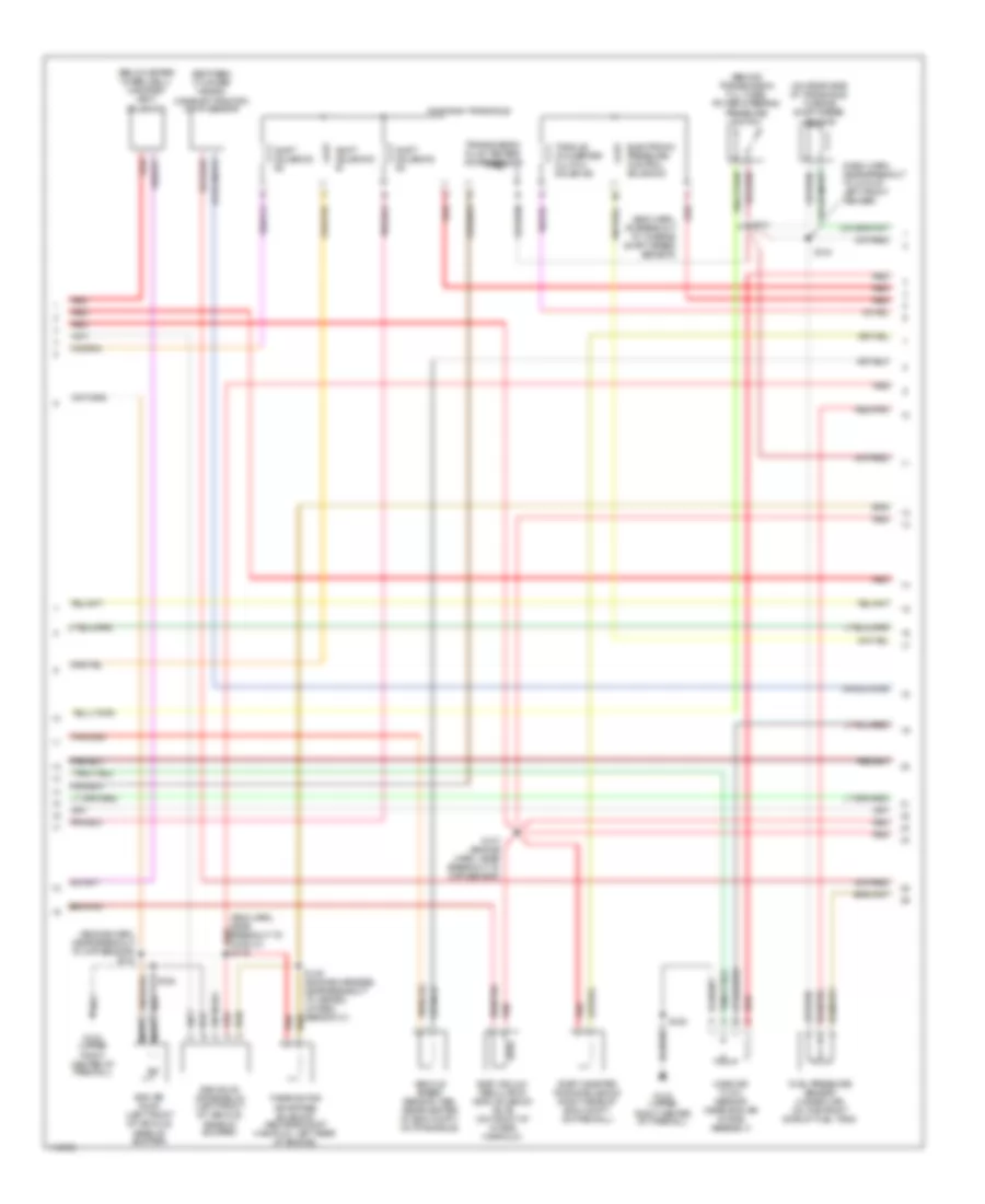
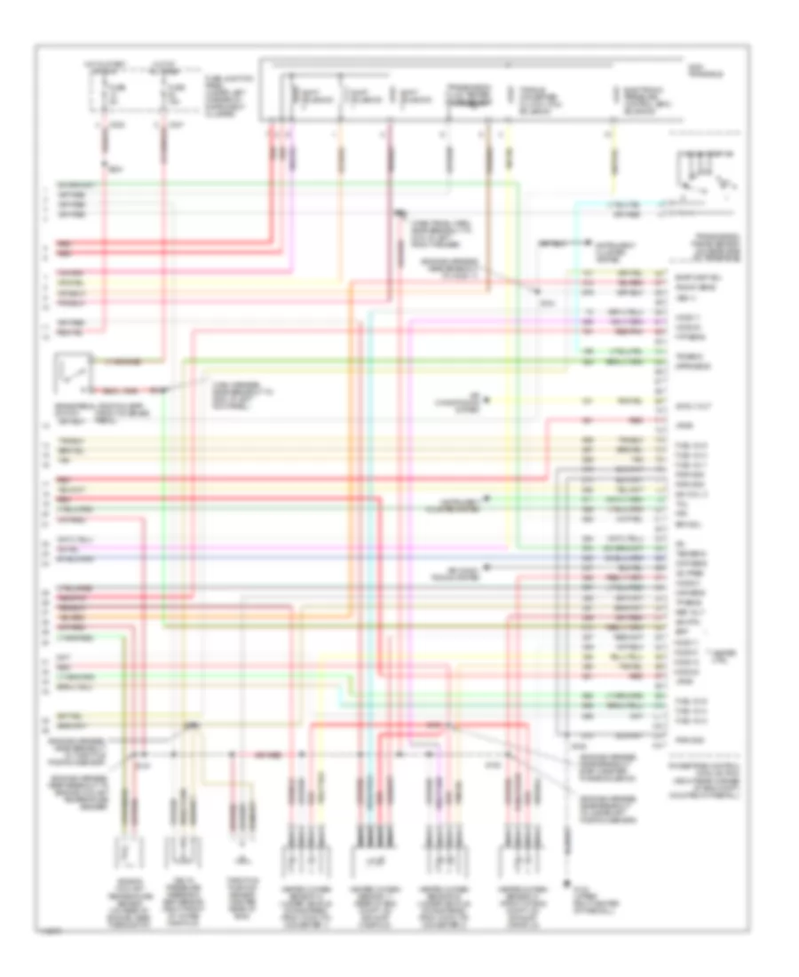
3.0L 12-Valve, Engine Performance Wiring Diagrams (1 of 3) for Mercury Sable GS 1999

List of elements for 3.0L 12-Valve, Engine Performance Wiring Diagrams (1 of 3) for Mercury Sable GS 1999:
- (below steering column)
- (dash panel harn, near breakout to g104 near left front fender)
- (engine harness, near breakout to fuel inj 5)
- (front center of eng compt, behind radiator)
- (left front fender)
- (left front fender, near air cleaner)
- (lower middle of right rear quarter panel) g405
- Accs
- Air conditioning system (a/c high press switch)
- Battery junction block
- C225
- C235
- C250
- C251
- Canister vent
- Case gnd
- Check engine indicator
- Ckp (+)
- Ckp (-)
- Cooling fans
- Cooling fans (high speed rly)
- Cooling fans (low speed rly)
- Crankshaft position sensor (on lower right front of engine)
- Data link connector
- Digital transmission range (dtr) sensor (on top of trans housing)
- Dlc
- Dlc bus (+)
- Dlc bus (-)
- Eam rly
- Ect
- Evr
- Fpm
- Fuel gauge
- Fuel gauge input
- Fuel pump relay
- Fuel pump/ fuel gauge sender (front side of
- Fuel tank)
- Fuse 10a
- Fuse 20a
- Fuse 30a
- Fuse 5a
- Fuse junction panel (under left corner of instrument cluster)
- G100
- G100 (left front fender)
- G104
- G123 (upper right center of firewall)
- High fan rly
- Ho2s 12
- Hot at all times
- Hot in start or run
- Iat
- Ign coil a
- Ign coil b
- Ignition coil
- Inertia fuel shut-off switch (behind right wheelwell)
- Instrument cluster
- Low fan rly
- Maf rtn
- Mil
- Nca
- Pcm diode
- Pcm relay
- Powertrain control module (pcm) (right rear corner of eng compt, on firewall)
- Psp
- Pwr gnd
- R n
- Radio noise capacitor (near ignition coil)
- Red
- S105
- S106
- S112
- S120
- S133
- S135
- S155
- S224
- S232 (left corner of dash)
- Ss 1
- Ss 2
- Ss 3
- Tach
- Tacho- meter
- Tft
- To dtr sensor (diagram 3 of 3)
- To spark plugs
- Tr1
- Tr2
- Tr4
- Vss (-)
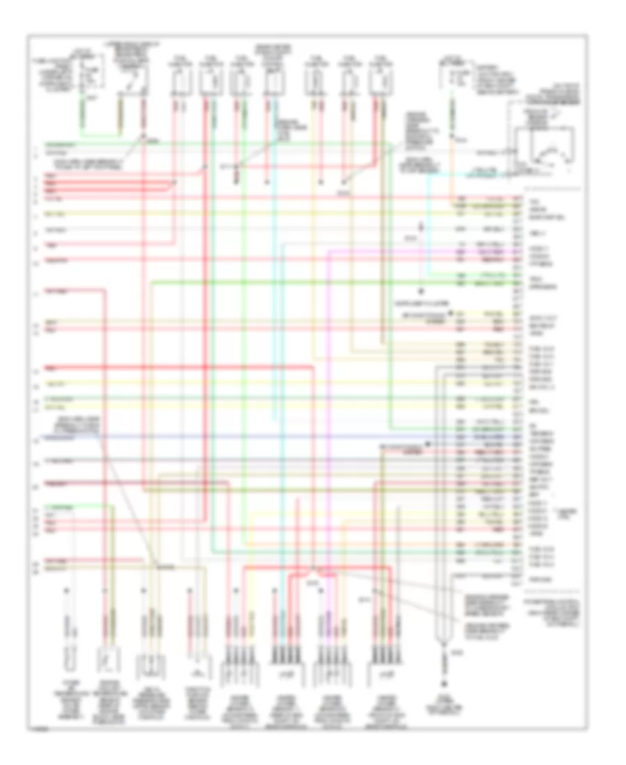
3.0L 12-Valve, Engine Performance Wiring Diagrams (2 of 3) for Mercury Sable GS 1999
List of elements for 3.0L 12-Valve, Engine Performance Wiring Diagrams (2 of 3) for Mercury Sable GS 1999:
- (behind transmission fill tube) power steering pressure switch
- (below spare wheelwell) canister vent
- (between cylinder heads) camshaft position (cmp) sensor
- (dash harn, near breakout to g104 at left front fender)
- (eng harn, at breakout to turbine shaft speed sensor)
- (eng harn, near breakout to ho2s 21) red s148
- (engine harn, near breakout to ckp sensor) s104
- (on rear side of transaxle) turbine shaft speed sensor
- Ax4s/ax4n transaxle
- Eam air pump (left front of vehicle, rear of bumper)
- Eam solid state relay (left front of vehicle, rear of bumper)
- Egr vacuum regulator (evr) solenoid valve (on front of intake manifold)
- Electronic pressure control solenoid
- Evap canister purge solenoid (right rear of eng compt, on firewall)
- Fuel pressure sensor (under car, on the front side of fuel tank)
- G123 (upper right center of firewall)
- Mass air flow sensor (near eng air intake assembly)
- Nca
- Red
- Red/pnk
- S101
- S106
- S107 (engine harn, near breakout to ckp sensor)
- S134
- S149 (engine harness, near breakout to heated oxygen sensor 21)
- S158
- Shift solenoid #1
- Shift solenoid #2
- Shift solenoid #3
- Solenoid
- Thermactor air bypass solenoid (above exhaust manifold, left rear of engine)
- Torque converter clutch solenoid
- Transmission fluid temper- ature sensor
- Vehicle speed sensor (vss) (rear center of eng compt, on transaxle)
3.0L 12-Valve, Engine Performance Wiring Diagrams (3 of 3) for Mercury Sable GS 1999
List of elements for 3.0L 12-Valve, Engine Performance Wiring Diagrams (3 of 3) for Mercury Sable GS 1999:
- heated oxygen sensor 21 (front of eng compt, on exhst manifold)
- (eng harn, near breakout to ckp sensor)
- (eng harn, near breakout to eng oil press switch)
- (engine harn, near fuel inj 5)
- (engine harness, near breakout to engine oil pressure switch)
- (engine harness, near breakout to fuel inj 6)
- (engine harness, near breakout to turbine shaft speed sensor)
- (front center of eng compt, behind battery)
- (main harn, near breakout to g200 at left kick panel)
- (on top of trans housing) digital transmission (dtr) range sensor
- (rear center of eng compt) idle air control valve
- (upper front side of brake pedal) brake pedal position (bpp) switch
- A/c pres
- Ac rly out
- Air conditioning system
- Battery junction box
- Bpp
- C247
- Cmp sens
- Delta pressure feedback egr (dpfe) sensor (on intake manifold)
- Dpfe sens
- Eam relay
- Engine coolant temperature sensor (rear of engine block, near thermostat)
- Epc sol
- Evap canp sol
- Fpm
- From dtr sensor (diagram 1 of 3)
- Ftp sens
- Fuel inj 1
- Fuel inj 2
- Fuel inj 3
- Fuel inj 4
- Fuel inj 5
- Fuel inj 6
- Fuel injector
- Fuse 15a
- Fuse junction panel (under left corner of instrument cluster)
- G123 (upper right center of firewall)
- Heated oxygen sensor 11 (rear of eng compt, on exhst manifold)
- Heated oxygen sensor 12 (downstream from cataltic conv 1)
- Heated oxygen sensor 22 (downstream from cataltic conv 2)
- Heater ctrl
- Ho2s 11
- Ho2s 12
- Ho2s 21
- Ho2s 22
- Hot at all times
- Iac
- Ign coil c
- Instrument cluster
- Intake air temperature sensor (on air intake assembly)
- Kapwr
- Maf sens
- Nca
- Ohms
- Powertrain control module (pcm) (right rear corner of eng compt, on firewall)
- Pwr gnd
- Red
- Red/pnk
- Ref volt
- S100
- S102
- S103
- S104
- S106
- S110
- S111
- S144
- S308
- Sig rtn
- Tan
- Tcc
- Throttle position sensor (behind intake manifold)
- Tp sens
- Tr3a
- Tss sens
- Vpwr
- Vss (+)
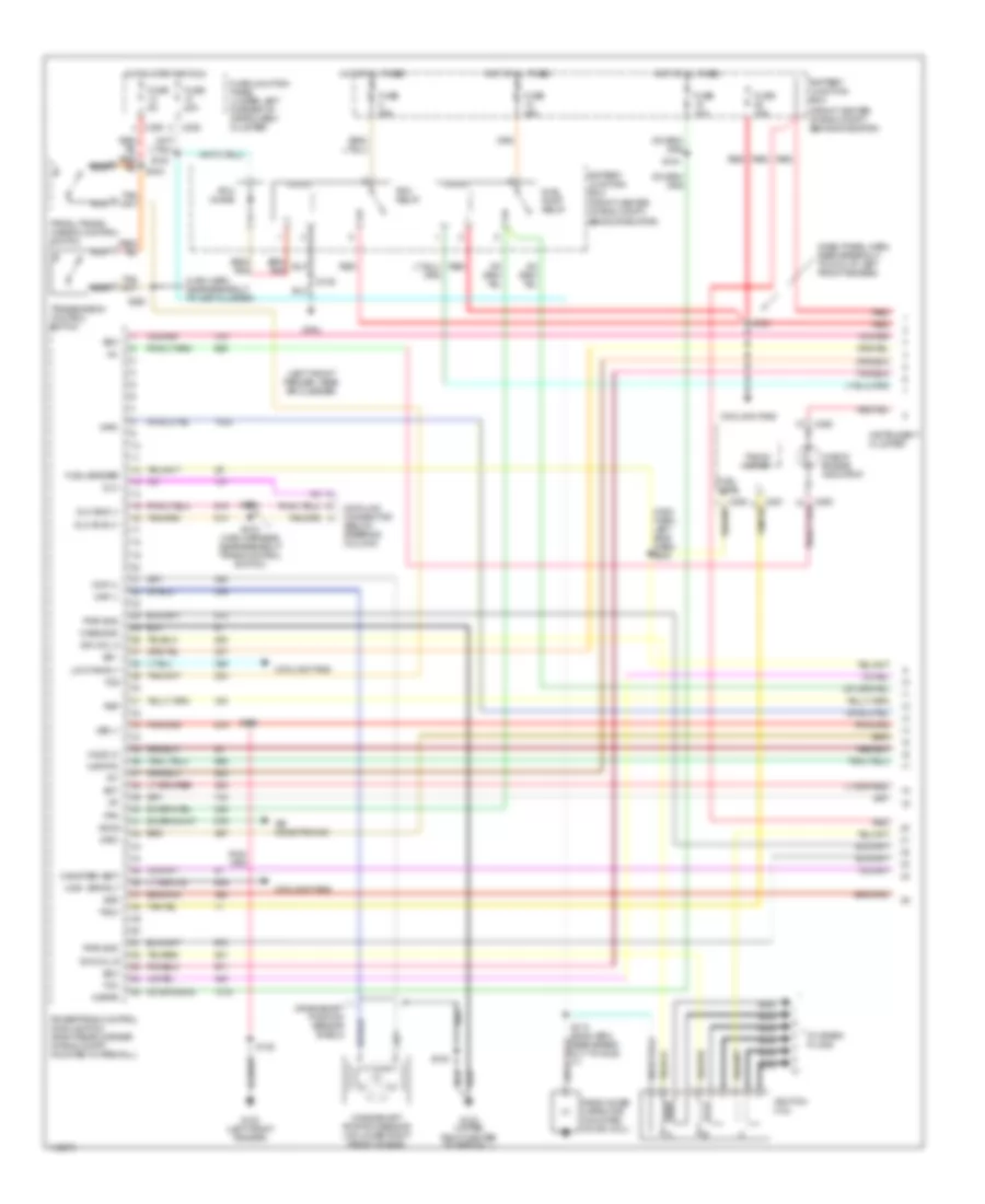
3.0L 24-Valve, Engine Performance Wiring Diagrams (1 of 3) for Mercury Sable GS 1999
List of elements for 3.0L 24-Valve, Engine Performance Wiring Diagrams (1 of 3) for Mercury Sable GS 1999:
- (dash panel harn, near breakout to g104 at left front fender)
- (front center of eng compt, behind radiator)
- (left front fender, near air cleaner)
- (main harn, left side dash) s232
- (main harn, near breakout to inst cluster)
- Accs
- Air conditioning
- Battery junction box
- C225
- C235
- C250
- Canister vent
- Case gnd
- Check engine indicator
- Ckp (+)
- Ckp (-)
- Cooling fans
- Crankshaft position sensor (on lower right front of eng)
- Crankshaft position sensor shield
- Data link connector (below steering column)
- Dlc
- Dlc bus (+)
- Dlc bus (-)
- Ect
- Evr
- Fpm
- Fuel level
- Fuel pump relay
- Fuel sender
- Fuse 10a
- Fuse 15a
- Fuse 20a
- Fuse 30a
- Fuse 5a
- Fuse junction panel (under left corner of instrument cluster)
- G100 (left front fender)
- G104
- G123 (upper right center of firewall)
- High spd rly
- Ho2s 12
- Hot at all times
- Hot in start or run
- Iat
- Ign coil a
- Ign coil b
- Ignition coil
- Imrc
- Instrument cluster
- Kapwr
- Low fan rly
- Maf rtn
- Mil
- Nca
- Pcm diode
- Pcm relay
- Powertrain control module (pcm) (right rear corner of eng compt, mounted in firewall)
- Prndl/trans- mission control switch
- Psp
- Pwr gnd
- Radio noise capacitor (mounted on ign coil)
- Red
- S105
- S108
- S112 (eng harn, near break- out to ho2s 11)
- S120
- S122
- S133
- S135
- S144
- S218 (main harness, near breakout trans control switch)
- S219
- S220
- Ss 1
- Ss 2
- Ss 3
- Tach
- Tacho- meter
- Tcc
- Tcs
- Tft
- To spark plugs
- Transmission control switch
- Vss (-)
3.0L 24-Valve, Engine Performance Wiring Diagrams (2 of 3) for Mercury Sable GS 1999
List of elements for 3.0L 24-Valve, Engine Performance Wiring Diagrams (2 of 3) for Mercury Sable GS 1999:
- (behind transmission fill tube) power steering pressure switch
- (below spare wheelwell) canister vent solenoid
- (engine harness, near breakout to engine coolant temperature sender)
- (engine harness, near breakout to heated oxygen sensor 11)
- (engine harness, near breakout to turbine shaft speed sensor)
- (left front of engine, below valve cover) camshaft position sensor
- (on rear side of transaxle) turbine shaft speed sensor
- (rear center of eng compt) idle air control valve
- Egr vacuum regulator (evr) solenoid valve (mounted on front of intake manifold)
- Evap canister purge solenoid (right rear of eng compt, mounted on firewall)
- Fuel injector
- Fuel pressure sensor (on front side of fuel tank)
- Fuel pump/ fuel gauge sender (on front side of fuel tank)
- G100 (left front fender)
- G123 (upper right center of firewall)
- G405 (lower middle section of rear quarter panel)
- Inertia fuel shut- off (ifs) switch (behind right rear wheelwell)
- Intake air temperature sensor (on air intake assembly)
- Intake manifold runner control (imrc) (on left side of engine mounted on valve cover)
- Knock sensor (left rear of eng, below intake manifold)
- Mass air flow sensor (in eng air intake assembly)
- Red
- Red/pnk
- S106
- S147
- S150
- S152
- Tan
- Vehicle speed sensor (vss) (rear center of eng compt, on transaxle)
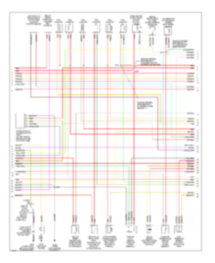
3.0L 24-Valve, Engine Performance Wiring Diagrams (3 of 3) for Mercury Sable GS 1999
List of elements for 3.0L 24-Valve, Engine Performance Wiring Diagrams (3 of 3) for Mercury Sable GS 1999:
- (dash panel harn, near breakout to g104 at left front fender)
- (engine harness, near breakout evap canister purge solenoid)
- (engine harness, near breakout to campshaft position sensor)
- (engine harness, near breakout to engine coolant temperature sender)
- (engine harness, near breakout to ho2s 11)
- (engine harness, near breakout to throttle position sensor)
- (front of brake pedal)
- (main harness, near breakout to g200 at left kick panel)
- A/c pres
- Ac rly out
- Air condi- tioning system
- Air conditioning system
- Ax4n transaxle
- Bpp
- Brake pedal position (bpp) switch
- C235
- C247
- Cmp sens
- D/2
- Delta pressure feedback egr sensor (right front of intake manifold)
- Dpfe sens
- Electronic pressure control (epc) solenoid
- Engine coolant temperature sensor (on rear of engine, near thermostat)
- Epc sol
- Evap canp sol
- Fpm
- Ftp sens
- Fuel inj 1
- Fuel inj 2
- Fuel inj 3
- Fuel inj 4
- Fuel inj 5
- Fuel inj 6
- Fuse 15a
- Fuse 5a
- Fuse junction panel (under left corner of instrument cluster)
- G123 (upper right center of firewall)
- Heated oxygen sensor 11 (rear of eng compt, on exhaust manifold)
- Heated oxygen sensor 12 (under vehicle, downstream, from catalytic converter 1)
- Heated oxygen sensor 21 (front of eng compt, on exhaust manifold)
- Heated oxygen sensor 22 (under vehicle, downstream, from catalytic converter 2)
- Heater ctrl
- Ho2s 11
- Ho2s 12
- Ho2s 21
- Ho2s 22
- Hot at all times
- Hot in start or run
- Iac
- Ign coil c
- Instrument cluster system
- Knock sens
- Maf sens
- Nca
- Powertrain control module (pcm) (right rear corner of eng compt, mounted in firewall)
- Pwr gnd
- Red
- Red/pnk
- Ref volt
- S102
- S104
- S106
- S134
- S151
- S153
- S157
- S224
- S308
- Shift solenoid
- Sig rtn
- Tan
- Tcil
- Throttle position sensor (center rear of eng)
- Torque converter clutch (tcc) solenoid
- Tp sens
- Tr sens
- Transmission fluid temper- ature sensor
- Transmission range sensor (on rear side of transaxle)
- Tss sens
- Vpwr
- Vss (+)