HORN
Horn Wiring Diagram for Ford E450 Super Duty 2005
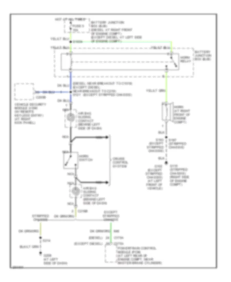
List of elements for Horn Wiring Diagram for Ford E450 Super Duty 2005:
- (diesel)
- (except diesel)
- (except stripped chassis)
- 15a
- Air bag sliding contact (behind left side of dash)
- Battery junction box (bjb)
- Battery junction box (bjb) (diesel: at right front of engine compt) (except diesel: at left side of engine compt)
- C175a
- C176a
- C203b
- C218b
- Cruise control system
- Except stripped chassis
- Fuse 5
- G102 (except stripped chassis) (at left front of vehicle)
- G115 (stripped chassis) (right side of engine compt)
- G208 (at left side of dash)
- Horn (at right front of engine compt)
- Horn relay
- Horn switch
- Hot at all times
- Nca
- Powertrain control module (pcm) (at left rear of engine compt, near master brake cylinder)
- S1034
- S163 (except stripped chassis)
- S197 (stripped chassis)
- S214
- Stripped chassis
- Vehicle security module (vsm) (w/ remote keyless entry) (at right kick panel)
 English