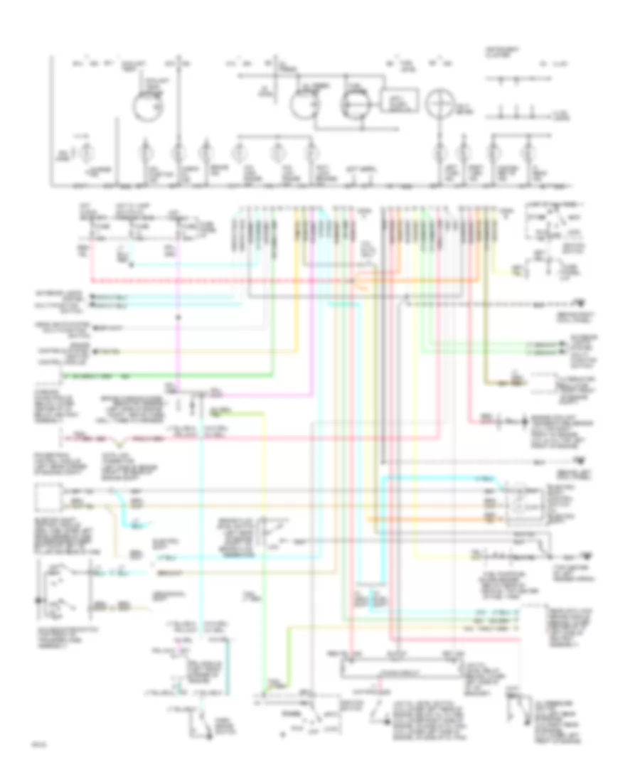
INSTRUMENT CLUSTER
Instrument Cluster Wiring Diagram, Sport for Ford Ranger Splash 1994

List of elements for Instrument Cluster Wiring Diagram, Sport for Ford Ranger Splash 1994:
- (behind left cowl panel)
- (behind right cowl panel)
- (below rear of
- (ignition
- (left rear of engine compt, on
- (left side of engine compt, above wheel
- (left side of engine compt, on rear of engine compt
- (multi-function
- (right front
- (top center of left fender apron)
- (w/ drl)
- (w/o drl)
- 3.0l & 4.0l only
- 4x4
- 4x4 high range ind.
- 4x4 indicator switch (top front of transfer case assembly)
- 4x4 low range ind.
- A10
- A11
- A12
- A13
- A14
- Acc
- Alternator/
- Anti- lock brakes ind.
- Anti- slosh module
- B10
- B11
- B12
- B13
- B14
- Brake fluid
- Brake ind.
- Brake warning diode/
- Charge ind.
- Check oil ind.
- Compt)
- Conn
- Control module)
- Controls system
- Coolant temp.
- Coolant temp. gauge
- Data link connector
- Drl module (left front corner of engine)
- Electric shift
- Electric shift control module (reg. cab-lower left rear corner of cab) (supercab-between bottom of left "b" pillar and rear of cab)
- Electric shift control switch (w/ electric shift)
- Engine
- Engine coolant temperature sensor (2.3l-top right front of engine) (3.0l & 4.0l-top left front of engine)
- Engine speed
- Exterior lights
- Exterior lights system (multi- function switch)
- Fasten belts ind.
- Fuel gauge
- Fuel level
- Fuel pump/fuel
- Fuse 10a
- Fuse 15a
- Fuse panel: i/p
- G104
- G200
- G203
- Gauge sender
- Gnd
- Headlights system
- Hi beam ind.
- Hot at all times
- Hot in run
- Hot in run or start
- Hot w/ lamp switch in park or head
- Ign
- Ignition switch
- Illum.
- Illum. lamps
- Instrument cluster
- Left turn ind.
- Level switch
- Lock
- Low
- Low oil level relay (behind lower left side of i/p, on bracket)
- Low oil level switch (2.3l-lower left rear of engine, below oil filter) (3.0l-lower right side of engine, on side of oil pan) (4.0l-lower left side of engine, on side of oil pan)
- Mal- function ind.
- Mechanical shift
- Of engine
- Of fuel tank)
- Off
- Off 4h
- Ohms
- Oil press.
- Oil press. gauge
- Oil pressure switch (2.3l-left rear of engine) (3.0l-right rear of engine) (4.0l-lower left front of engine)
- Park brake switch
- Powertrain control module (left rear corner of engine compt)
- Rear anti-lock brake module (behind lower center of i/p, left side of ashtray assembly)
- Regulator
- Reservoir)
- Resistor assembly
- Right turn ind.
- Run
- Start
- Switch)
- System
- Tacho- meter
- Timing circuit
- Vehicle, top center
- Volt- meter
- W/ drl
- W/ elec. shift
- W/ mech. shift
- W/o drl
- Warning chime module (below lower center of i/p, below ashtray assembly)
- Well, taped in harness)
Instrument Cluster Wiring Diagram, Standard for Ford Ranger Splash 1994
List of elements for Instrument Cluster Wiring Diagram, Standard for Ford Ranger Splash 1994:
- (behind left cowl panel)
- (behind right cowl panel)
- (below rear of
- (ignition
- (left rear of engine compt, on
- (left side of engine compt, above wheel
- (left side of engine compt, on rear of engine compt
- (multi-function
- (not used)
- (right front
- (top center of left fender apron)
- (w/ drl)
- (w/o drl)
- 3.0l & 4.0l only
- 4x4
- 4x4 high range ind.
- 4x4 indicator switch (top front of transfer case assembly)
- 4x4 low range ind.
- A10
- A11
- A12
- A13
- A14
- Acc
- Alternator/
- Anti- lock brakes ind.
- Anti- slosh module
- B10
- B11
- B12
- B13
- B14
- Brake fluid
- Brake ind.
- Brake warning diode/
- Charge ind.
- Check oil ind.
- Compt)
- Conn
- Control module)
- Controls system
- Coolant temp.
- Coolant temp. gauge
- Data link connector
- Drl module (left front corner of engine)
- Electric shift
- Electric shift control module (reg. cab-lower left rear corner of cab) (supercab-between bottom of left "b" pillar and rear of cab)
- Electric shift control switch (w/ electric shift)
- Engine
- Engine coolant temperature sensor (2.3l-top right front of engine) (3.0l & 4.0l-top left front of engine)
- Exterior lights
- Exterior lights system (multi- function switch)
- Fasten belts ind.
- Fuel gauge
- Fuel level
- Fuel pump/fuel
- Fuse 10a
- Fuse 15a
- Fuse panel: i/p
- G104
- G200
- G203
- Gauge sender
- Gnd
- Headlights system
- Hi beam ind.
- Hot at all times
- Hot in run
- Hot in run or start
- Hot w/ lamp switch in park or head
- Ign
- Ignition switch
- Illum.
- Illum. lamps
- Instrument cluster
- Left turn ind.
- Level switch
- Lock
- Low
- Low oil level relay (behind lower left side of i/p, on bracket)
- Low oil level switch (2.3l-lower left rear of engine, below oil filter) (3.0l-lower right side of engine, on side of oil pan) (4.0l-lower left side of engine, on side of oil pan)
- Mal- function ind.
- Mechanical shift
- Of engine
- Of fuel tank)
- Off
- Off 4h
- Ohms
- Oil press.
- Oil press. gauge
- Oil pressure switch (2.3l-left rear of engine) (3.0l-right rear of engine) (4.0l-lower left front of engine)
- Park brake switch
- Powertrain control module (left rear corner of engine compt)
- Rear anti-lock brake module (behind lower center of i/p, left side of ashtray assembly)
- Regulator
- Reservoir)
- Resistor assembly
- Right turn ind.
- Run
- Start
- Switch)
- System
- Timing circuit
- Vehicle, top center
- Volt- meter
- W/ drl
- W/ elec. shift
- W/ mech. shift
- W/o drl
- Warning chime module (below lower center of i/p, below ashtray assembly)
- Well, taped in harness)