NAVIGATION
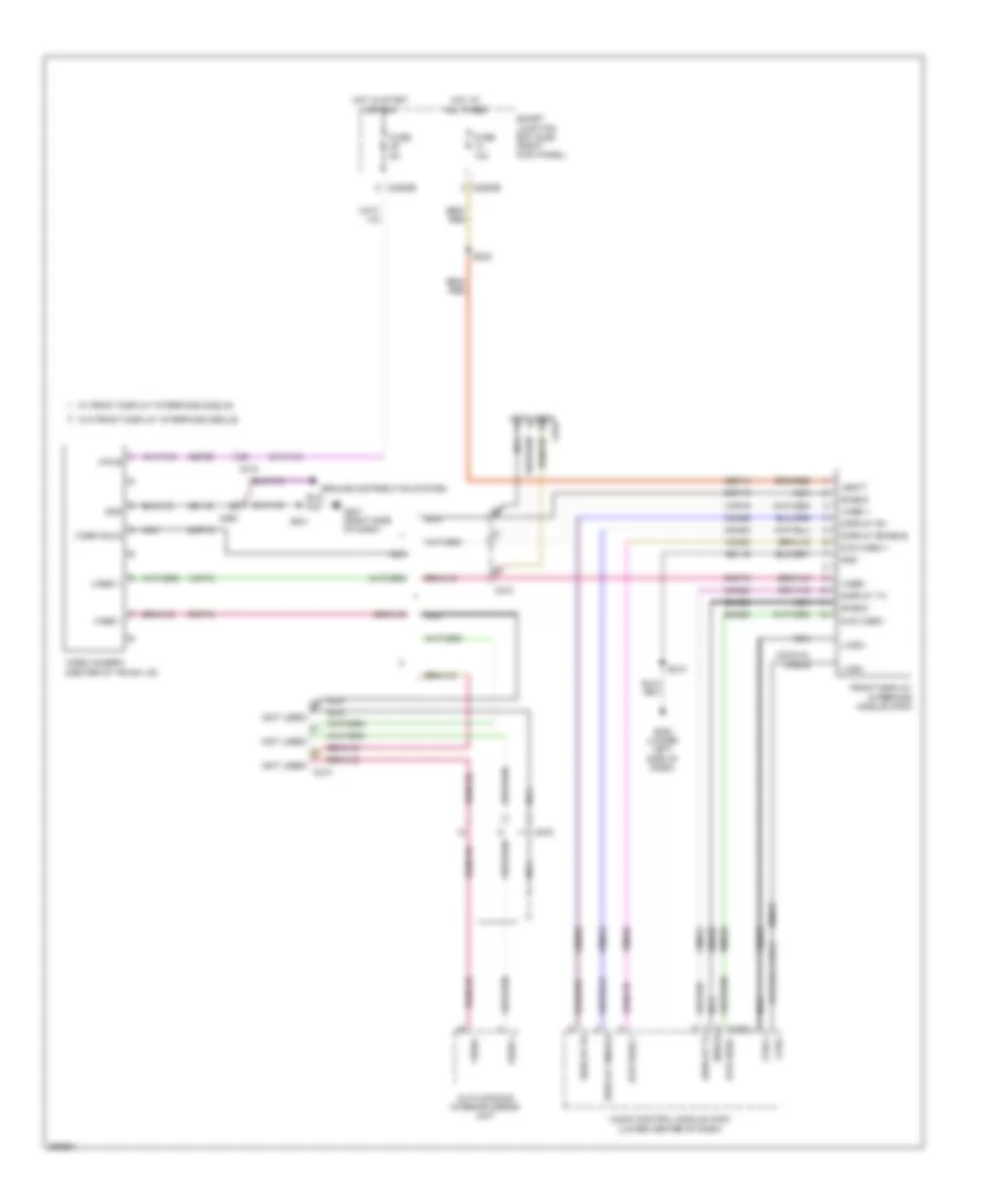
Navigation Wiring Diagram (1 of 3) for Ford Mustang GT 2013

List of elements for Navigation Wiring Diagram (1 of 3) for Ford Mustang GT 2013:
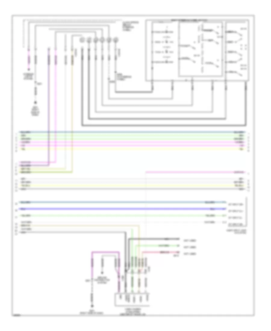
Navigation Wiring Diagram (2 of 3) for Ford Mustang GT 2013
List of elements for Navigation Wiring Diagram (2 of 3) for Ford Mustang GT 2013:
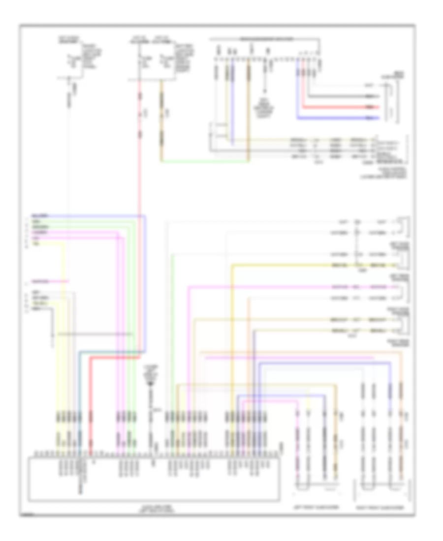
Navigation Wiring Diagram (3 of 3) for Ford Mustang GT 2013
List of elements for Navigation Wiring Diagram (3 of 3) for Ford Mustang GT 2013:
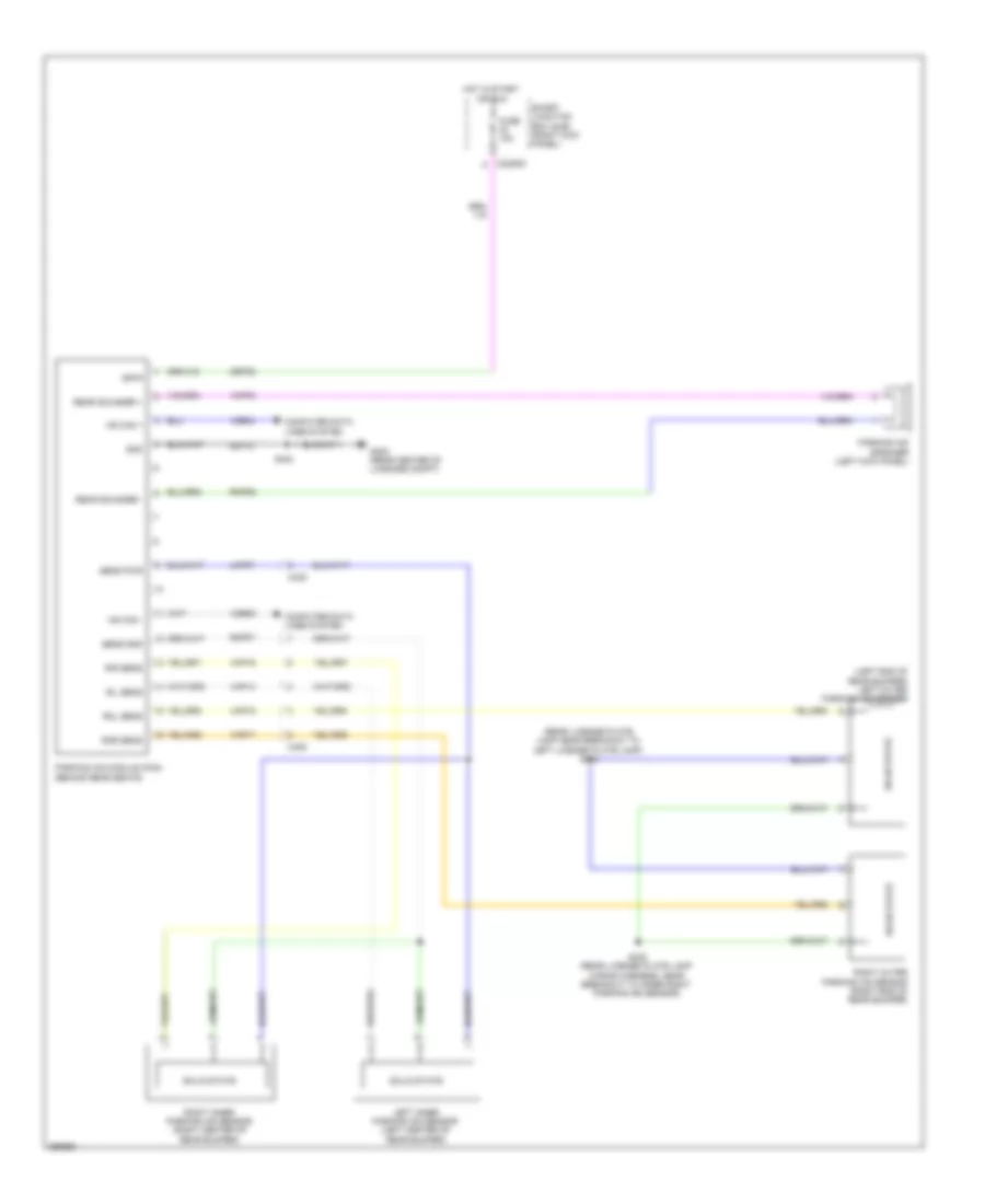
Parking Assistant Wiring Diagram for Ford Mustang GT 2013
List of elements for Parking Assistant Wiring Diagram for Ford Mustang GT 2013:
Rear Camera Wiring Diagram for Ford Mustang GT 2013
List of elements for Rear Camera Wiring Diagram for Ford Mustang GT 2013: