PASSIVE RESTRAINTS
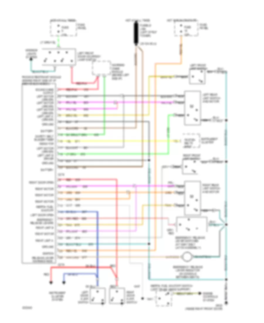
Passive Restraint Wiring Diagram for Ford Tempo GL 1994
List of elements for Passive Restraint Wiring Diagram for Ford Tempo GL 1994:
- Battery
- C278
- C279
- Emergency release lever indicator (in console between seats)
- Emergency release lever switches (at seat belt latch assembly)
- Emergency release levers
- Engine controls system
- Fasten belts input
- Fuse 10a
- Fuse 15a
- Fuse panel
- Fusible link (left strut tower)
- Ground
- Hot at all times
- Hot in run or start
- Ignition
- Inertia fuel shutoff
- Inertia fuel shutoff switch (left trunk hinge support)
- Instrument cluster
- Instrument cluster system
- Interior lights system
- Left door ajar switch
- Left door open
- Left front door courtesy lamp switch
- Left front limit switch
- Left motor (driver) left limit b driver
- Left rear limit switch and motor
- Nca
- Passive restraint module (behind right side of i/p above glove box)
- Red
- Red/pnk
- Release lever warning indic.
- Right door ajar switch
- Right door open
- Right front limit switch
- Right limit a
- Right limit b
- Right motor
- Right rear limit switch and motor
- Safety belt buzzer timer indicator
- Sound chime output left motor (driver) left motor (driver) left motor (driver) left limit a (driver)
- Tan
- Warning chime module (behind left side i/p)
 English