POWER DISTRIBUTION
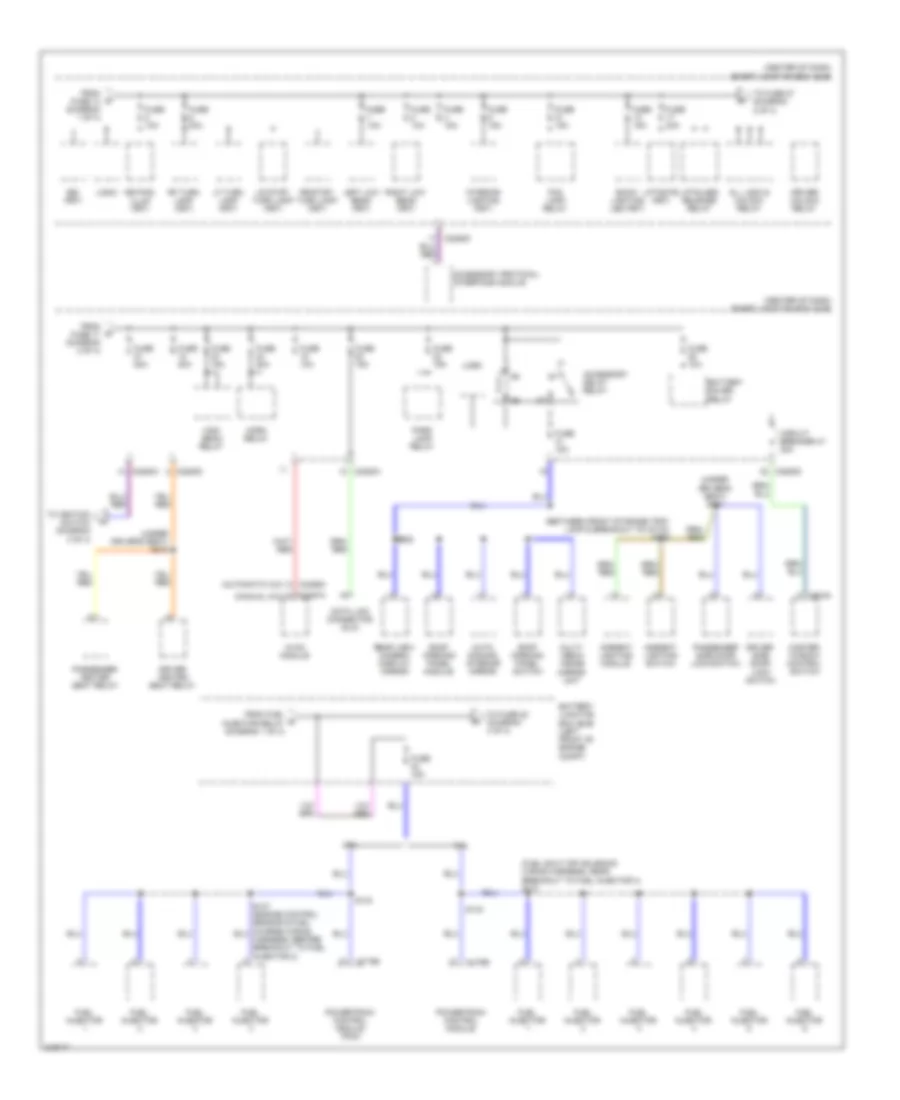
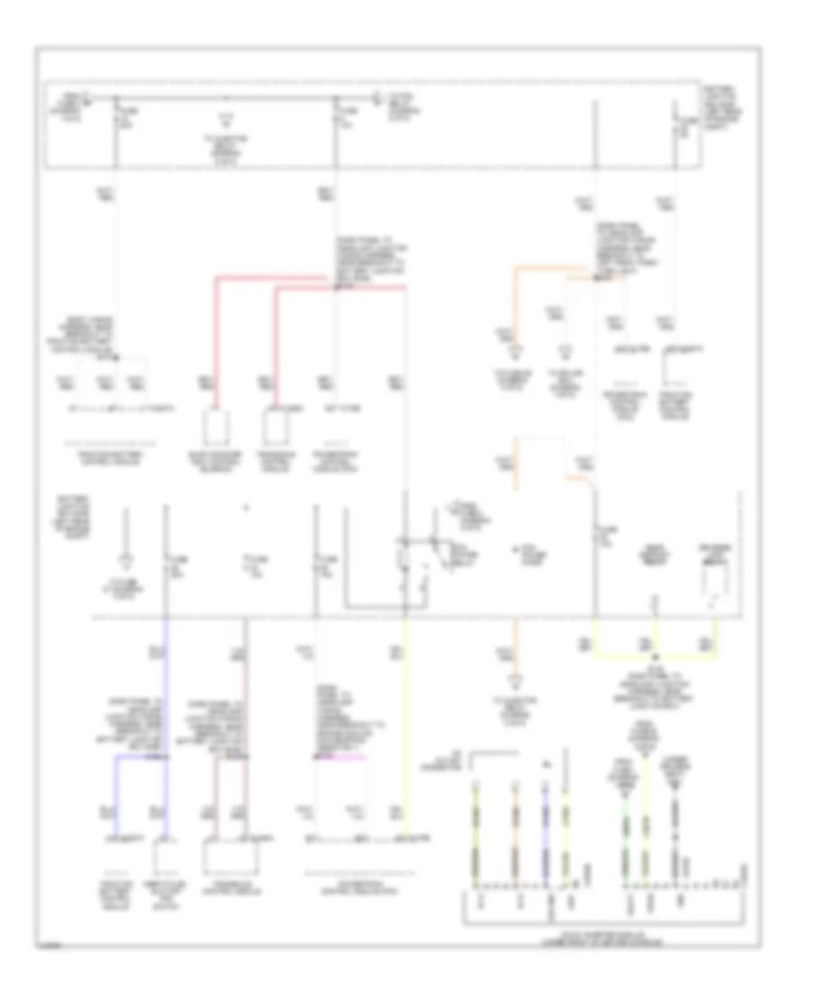
Power Distribution Wiring Diagram, Except Hybrid (1 of 4) for Ford Escape 2010

List of elements for Power Distribution Wiring Diagram, Except Hybrid (1 of 4) for Ford Escape 2010:
- (engine control sensor & fuel charge wiring harness, before breakout to g109) s150
- (left front of engine compt) battery junction box (bjb)
- 175a
- 2.5l
- 3.0l
- 4x4 control module
- A/c clutch relay
- Anti-lock brake system (abs) module
- Audio amplifier
- Audio control module (acm)
- Battery
- Battery junction box (bjb) (left front of engine compt)
- Blower motor relay
- Brake pedal position switch
- C1035a
- C1035b
- C1035c
- C175b
- C2231b
- C2280a
- C2280b
- C2280d
- C2280g
- C240a
- C3154b
- Cable pro/ fusible link
- Console power point
- Cooling fan low speed relay
- Cooling fan relay
- Evap canister vent control solenoid
- Exterior rear view mirror switch
- From fuse 14 (diagram 1 of 4)
- Front controls interface module (fcim)
- Front display interface module (fdim)
- Fuel injector diode
- Fuel injector relay
- Fuse 10a
- Fuse 15a
- Fuse 20a
- Fuse 25a
- Fuse 30a
- Fuse 40a
- Fuse 50a
- Fuse 7.5a
- G104 (left front of engine compt)
- G201 (right side of dash)
- G302 (right "a" pillar)
- Generator
- Global positioning system module (gpsm) (w/ sysn & gpsm)
- Instrument cluster
- Left seat control switch
- Liftgate lock relay
- Midi fuse 125a
- Midi fuse 80a
- Pcm power relay
- Pnk
- Power point
- Power steering control module (pscm)
- Powertrain control module (pcm)
- Rear window defrost relay
- Rear wiper motor assembly
- Red
- Reverse lamp relay
- Roof opening panel module
- S109
- S140
- S233
- S238 (w/ sysn & gpsm) (left side of instrument panel)
- S339 (w/ ambient lighting)
- Smart junction box (sjb) (center of dash)
- Starter motor
- Starter relay
- Subwoofer amplifier
- To fuse 23 (diagram 2 of 4)
- To fuse 5 (diagram 2 of 4)
- To midi fusible link (diagram 1 of 4)
- To splice s113 (diagram 3 of 4)
- Trailer tow left turn relay
- Trailer tow park lamp relay
- Trailer tow right turn relay
- W/ sysn & gpsm
- W/o sysn & gpsm
- Windshield wiper motor
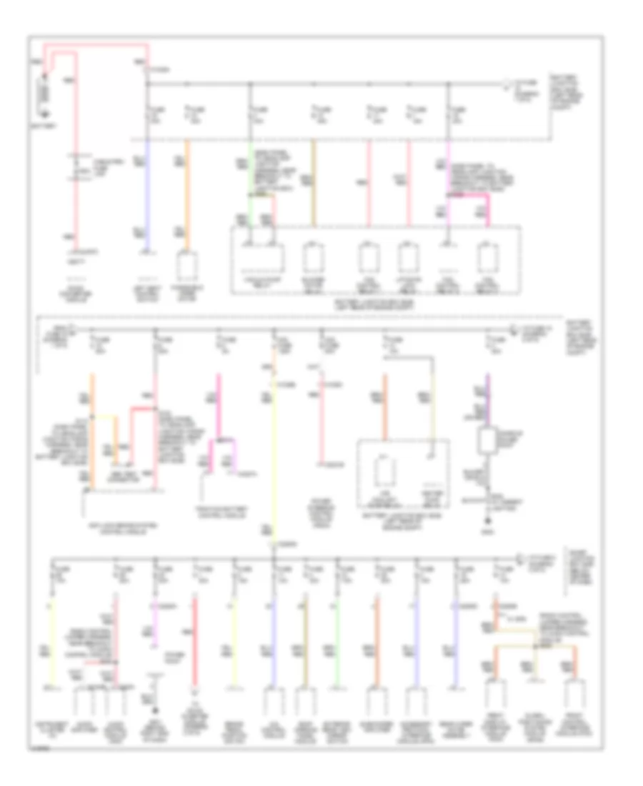
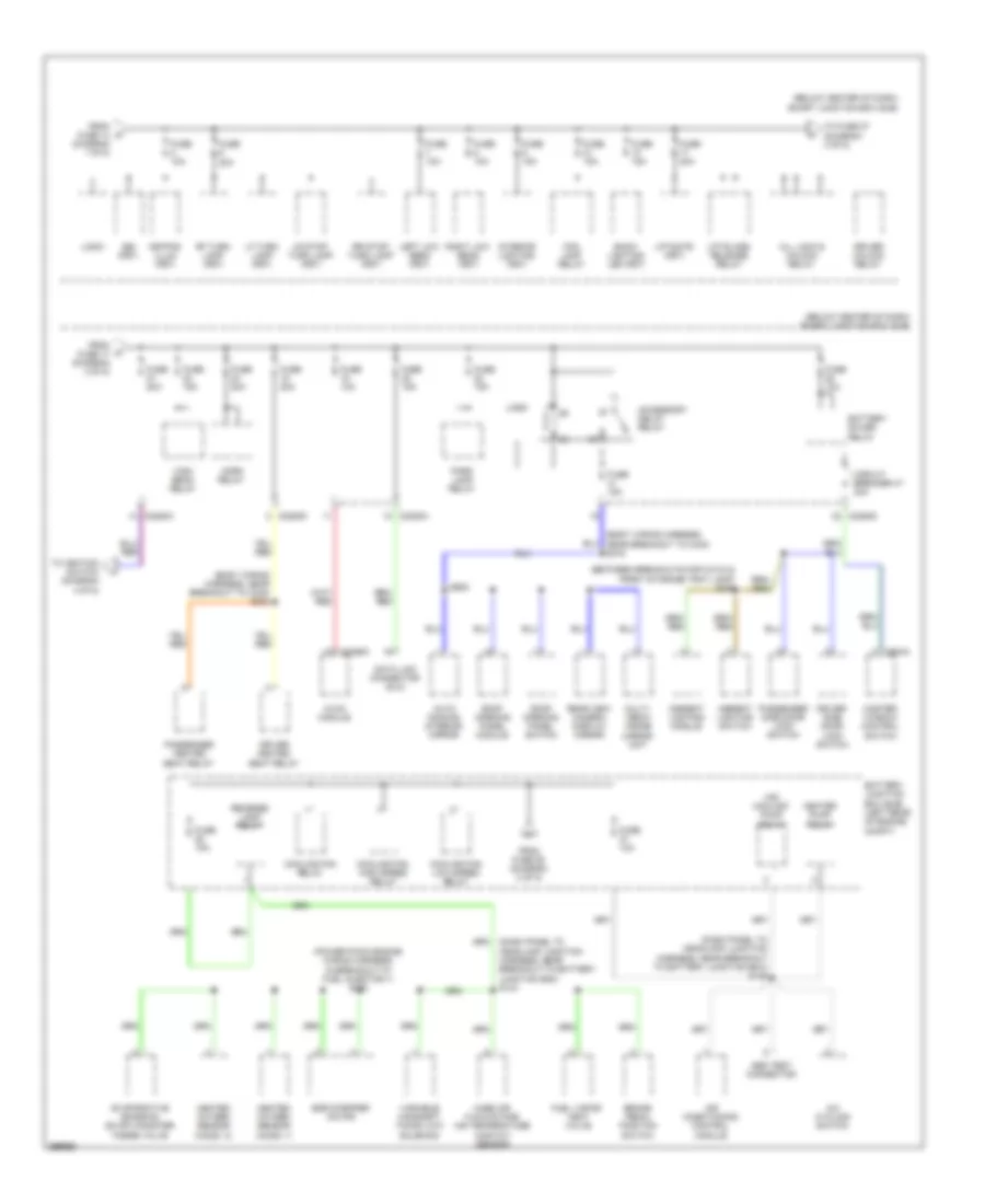
Power Distribution Wiring Diagram, Except Hybrid (2 of 4) for Ford Escape 2010
List of elements for Power Distribution Wiring Diagram, Except Hybrid (2 of 4) for Ford Escape 2010:
- (automatic a/c)
- (between front storage tray lamp & breakout to c3134) s345
- (center of dash) smart junction box (sjb)
- (fuel shut off solenoid wiring harness, near breakout to fuel injector 4) s131
- (manual a/c)
- (under driver's seat) s317
- (under driver's seat) s318
- 2.5l
- 3.0l
- Accessory delay relay
- Accessory protocol interface module
- All lock & unlock relay
- Ambient lighting module
- Ambient lighting switch
- Auto- dimming interior mirror
- Back- lighting led (fet)
- Battery junction box (bjb) (left front of engine compt)
- Battery saver relay
- Bsi (fet)
- C175b
- C2280a
- C2280d
- C2356a
- C2357a
- C504a
- Circuit breaker 47 30a
- Data link connector (dlc)
- Driver heated seat relay
- Driver side door lock switch
- Driver unlock relay
- Fog lamp relay
- From fuel b injector relay (diagram 1 of 4)
- From fuse 14 (diagram 1 of 4)
- From fuse 17 (diagram 2 of 4)
- Fuel injector
- Fuse 10a
- Fuse 15a
- Fuse 20a
- High beam relay
- Horn relay
- Hvac module
- Interior lighting (fet)
- Keypad illum (fet)
- Left low beam (fet)
- Lf turn lamp (fet)
- Liftgate (fet)
- Liftglass release relay
- Logic
- Lr stop/ turn lamp (fet)
- Master window control switch
- Multi- media inside mirror unit
- Park lamp relay
- Passenger heated seat relay
- Passenger side door lock switch
- Powertrain control module
- Powertrain control module (pcm)
- Rear view camera display mirror
- Rf turn lamp (fet)
- Right low beam (fet)
- Roof opening panel module
- Roof opening panel switch
- Rr stop/ turn lamp (fet)
- S143
- S905
- To fuse 22 (diagram 4 of 4)
- To fuse 27 (diagram 2 of 4)
- To ignition switch (diagram 3 of 4)
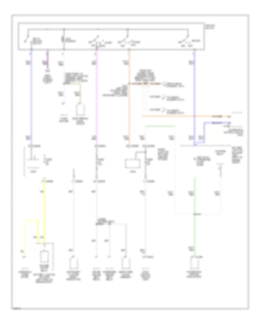
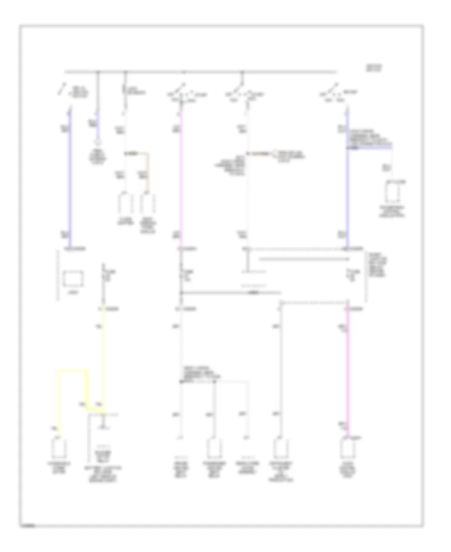
Power Distribution Wiring Diagram, Except Hybrid (3 of 4) for Ford Escape 2010
List of elements for Power Distribution Wiring Diagram, Except Hybrid (3 of 4) for Ford Escape 2010:
- (dash panel to headlamp junction harness, near breakout to c2070) s229
- (headlamp jumper wiring harness, near breakout to left front side lamp) s113
- (under driver's seat) s306
- Acc
- Audio control module (acm)
- Battery junction box (bjb) (left front of engine compt)
- Blower motor relay
- C175b
- C2280a
- C2280b
- C2280d
- C2280e
- C240a
- Driver heated seat relay
- Floor shifter
- From fuse 27 (diagram 2 of 4)
- From fuse 35 (diagram 1 of 4)
- Fuse 10a
- Fuse 5a
- Ignition switch
- Instrument cluster (early production)
- Key in ignition switch
- Lock solenoid
- Logic
- Off
- One touch integrated start diode
- Passenger heated seat relay
- Powertrain control module (pcm)
- Rear wiper motor assembly
- Roof opening panel module
- Run
- S141
- S213 (left side of instrument panel, near instrument cluster)
- Smart junction box (sjb) (center of dash)
- Start
- Starter relay
- To fuse 25 (diagram 4 of 4)
- To fuse 29 (diagram 4 of 4)
- Windshield wiper motor
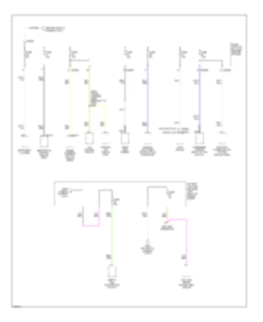
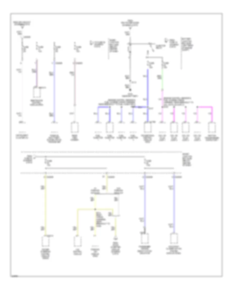
Power Distribution Wiring Diagram, Except Hybrid (4 of 4) for Ford Escape 2010
List of elements for Power Distribution Wiring Diagram, Except Hybrid (4 of 4) for Ford Escape 2010:
- (automatic a/c)
- (body wiring harness, near breakout to c340) s323
- (diagram 2 of 4)
- (manual a/c)
- 4x4 control module
- Abs test connector
- Anti-lock brake system (abs) module
- Battery junction box (bjb) (left front of engine compt)
- C2041a
- C2231a
- C2280b
- C2280d
- C2280e
- C2356a
- C2357a
- From fuse 23 g
- From splice s113 (diagram 3 of 4)
- Fuse 10a
- Fuse 20a
- Fuse 5a
- Fuse 7.5a
- Hvac module
- Inertia fuel shutoff (ifs) switch
- Instrument cluster
- Nca
- Occupant classification system module (ocsm)
- Parking aid module (pam)
- Passenger air bag deactivation switch
- Passive anti-theft system (pats) tranceiver
- Power steering control module (pscm)
- Rear view camera
- Restraints control module (rcm)
- Smart junction box (sjb) (center of dash)
Power Distribution Wiring Diagram, Hybrid (1 of 5) for Ford Escape 2010
List of elements for Power Distribution Wiring Diagram, Hybrid (1 of 5) for Ford Escape 2010:
- (dash panel to headlamp junction harness, near breakout to battery junction box) s155
- (dash panel to headlamp junction wiring harness, near breakout to battery junction box (bjb)) s125
- (diagram 2 of 5)
- (radio control jumper harness, near breakout to audio control module) s233
- (radio control jumper harness, near breakout to audio control module) s238
- 150a
- 4x4 control module
- Abs test connector
- Accessory protocol interface module (apim)
- Anti-lock brake system control module
- Audio amplifier
- Audio control module (acm)
- Battery
- Battery junction box (bjb) (left rear of engine compt)
- Blower motor relay
- Brake pedal position switch
- C1035a
- C1035b
- C1035c
- C1457c
- C2231b
- C2280a
- C2280b
- C2280d
- C2280g
- C240a
- C3154b
- C4227a
- Cable pro/ fuse link
- Console power point
- Dc/dc converter module
- Exterior rear view mirror switch
- Fan control relay 1
- Fan control relay 2
- Fan control relay 3
- From fuse 16 (diagram 1 of 5)
- Front control interface module (fcim)
- Front display interface module (fdim)
- Fuse 10a
- Fuse 15a
- Fuse 20a
- Fuse 25a
- Fuse 30a
- Fuse 40a
- Fuse 50a
- Fuse 5a
- Fuse 7.5a
- G201 (behind right end of dash)
- G302
- Global positioning system module (gpms)
- Heater pump relay
- Instrument cluster (ic)
- Left seat control switch
- Liftgate lock relay
- M/e coolant pump relay
- Midi fuse 125a
- Midi fuse 80a
- Power point
- Power steering control module (pscm)
- Rear wiper motor assembly
- Red
- Roof opening panel module
- S112 (dash panel to headlamp junction wiring harness, near breakout to battery junction box (bjb))
- S123 (dash panel to headlamp junction wiring harness, near breakout to battery junction box (bjb))
- S348 (w/ ambient lighting)
- S414
- Smart junction box (sjb) (below center of dash)
- Subwoofer amplifier
- To dc/ac inverter module
- To fuse (diagram 1 of 5)
- To fuse 15 (diagram 2 of 5)
- To fuse 5 (diagram 3 of 5)
- Traction battery control module
- Vacuum pump relay
- Vbatt
- W/ gps
- Windshield wiper motor
Power Distribution Wiring Diagram, Hybrid (2 of 5) for Ford Escape 2010
List of elements for Power Distribution Wiring Diagram, Hybrid (2 of 5) for Ford Escape 2010:
- (body wiring harness, near breakout to traction battery control module) s410
- (dash panel to headlamp junction wiring harness, near breakout to battery junction box (bjb))
- (dash panel to headlamp junction wiring harness, near breakout to battery junction box (bjb)) s116
- (dash panel to headlamp junction wiring harness, near breakout to battery junction box (bjb)) s142
- (dash panel to headlamp junction wiring harness, near breakout to left front park/ turn light) s107
- (dash panel to headlamp wiring harness, near breakout to engine cooling fan dropping resistor 1) s132
- (under driver's seat) g301
- Ac outlet connector
- Ac-a
- Ac-b
- Battery junction box (bjb) (left rear of engine compt)
- C1458a
- C175b
- C2293a
- C2293b
- C4227a
- Cbp35
- Dc/ac inverter module (under front of center console)
- Evap canister vent control solenoid
- From fuse 1 (diagram 1 of 5)
- From fuse 3 (diagram 1 of 5)
- From fuse 35 (diagram 5 of 5)
- From fuse 5 (diagram 2 of 5)
- Fuse 10a
- Fuse 15a
- Fuse 20a
- Fuse 50a
- Fuse 5a
- Gd182
- Gnd
- Hya01
- Hya02
- Inertia fuel shutoff (ifs) switch
- Led gnd
- Led+
- Lya03
- Pcm power diode
- Pcm power relay
- Powertrain control module (pcm)
- Rear defrost relay
- Reverse lamp relay
- Rya03
- S122
- S145 (dash panel to headlamp junction harness, near breakout to battery junction box)
- Sbp04
- To fuse 27 (diagram 3 of 5)
- To fuse 29 (diagram 5 of 5)
- To injector relay (diagram 5 of 5)
- To pcm relay (diagram 2 of 5)
- To splice s213 (diagram 4 of 5)
- Traction battery control module
- Transaxle control module
- Vbatt
- Vpwr
Power Distribution Wiring Diagram, Hybrid (3 of 5) for Ford Escape 2010
List of elements for Power Distribution Wiring Diagram, Hybrid (3 of 5) for Ford Escape 2010:
- (below center of dash) smart junction box (sjb)
- (between breakouts for c3134 & front storage tray lamp) s346
- (body wiring harness, near breakout to c340) s316
- (body wiring harness, near breakout to c340) s333
- (dash panel to headlamp junction harness, near breakout to battery junction box) s146
- (power pack engine wiring harness, in breakout to fuel injector 1) s100
- A/c cycling switch
- Abs test connector
- Accessory delay relay
- Air conditioning control module
- All lock & unlock relay
- Ambient lighting module
- Ambient lighting switch
- Auto dimming interior mirror
- Back- lighting led (fet)
- Battery junction box (bjb) (left rear of engine compt)
- Battery saver relay
- Brake pedal position switch
- Bsi (fet)
- C2280a
- C2280d
- C2356a
- C504a
- Circuit breaker 47 30a
- Cooling fan high speed relay
- Cooling fan low speed relay
- Cooling fan relay
- Data link connector (dlc)
- Driver heated seat relay
- Driver side door lock switch
- Driver unlock relay
- Egr stepper motor
- Evaporative emission (evap) canister purge valve
- Fog lamp relay
- From fuse 14 (diagram 1 of 5)
- From fuse 17 (diagram 3 of 5)
- From fuse 26 (diagram 2 of 5)
- Fuel vapor vent valve
- Fuse 10a
- Fuse 15a
- Fuse 20a
- Heated oxygen sensor (ho2s) 11
- Heated oxygen sensor (ho2s) 12
- Heater pump relay
- High beam relay
- Horn relay
- Hvac module
- Interior lighting (fet)
- Keypad illum (fet)
- Left low beam (fet)
- Lf turn lamp (fet)
- Liftgate (fet)
- Liftglass release relay
- Logic
- Lr stop/ turn lamp (fet)
- M/e coolant pump relay
- Mass air flow/intake air temperature (maf/iat) sensor
- Master window control switch
- Multi- media inside mirror unit
- Park lamp relay
- Passenger heated seat relay
- Passenger side door lock switch
- Rear view camera display mirror
- Reverse lamp relay
- Rf turn lamp (fet)
- Right low beam (fet)
- Roof opening panel module
- Roof opening panel switch
- Rr stop/ turn lamp (fet)
- S905
- To fuse 27 (diagram 3 of 5)
- To ignition switch (diagram 4 of 5)
- Variable camshaft timing (vct) solenoid
Power Distribution Wiring Diagram, Hybrid (4 of 5) for Ford Escape 2010
List of elements for Power Distribution Wiring Diagram, Hybrid (4 of 5) for Ford Escape 2010:
- (body wiring harness, near breakout to c339) s313
- Acc
- Audio control module (acm)
- Battery junction box (bjb) (left rear of engine compt)
- Blower motor relay
- C175b
- C2280a
- C2280b
- C2280d
- C2280e
- C240a
- Driver heated seat relay
- Floor shifter
- From fuse 27 (diagram 3 of 5)
- From splice s107 (diagram 2 of 5)
- Fuse 10a
- Fuse 5a
- Ignition switch
- Instrument cluster (ic) (early production)
- Key in ignition switch
- Lock solenoid
- Logic
- Off
- Passenger heated seat relay
- Powertrain control module (pcm)
- Rear wiper motor assembly
- Roof opening panel module
- Run
- S213 (main wiring harness, near breakout to c212)
- S229
- Smart junction box (sjb) (below center of dash)
- Start
- Windshield wiper motor
Power Distribution Wiring Diagram, Hybrid (5 of 5) for Ford Escape 2010
List of elements for Power Distribution Wiring Diagram, Hybrid (5 of 5) for Ford Escape 2010:
- (engine control sensor & fuel charge wiring harness, near breakout to coil on plug (cop) 3) s102
- (engine control sensor & fuel charge wiring harness, near breakout to fuel injector 3) s106
- 4x4 control module
- Battery junction box (bjb) (left rear of engine compt)
- C175b
- C2041a
- C2231a
- C2280b
- C2280d
- C2280e
- Coil on plug (cop) 1
- Coil on plug (cop) 2
- Coil on plug (cop) 3
- Coil on plug (cop) 4
- From dc/ac inverter module (diagram 2 of 5)
- From fuse 15 (diagram 2 of 5)
- From fuse 32 (diagram 5 of 5)
- From pcm power diode (diagram 2 of 5)
- From splice s107 (diagram 2 of 5)
- Fuel injector
- Fuse 10a
- Fuse 15a
- Fuse 5a
- Fuse 7.5a
- G104 (near battery)
- Ignition transformer capacitor 1
- Injector relay
- Instrument cluster (ic)
- Nca
- Occupant classification system module (ocsm)
- Parking aid module (pam)
- Passenger air bag deactivation indicator
- Passive anti-theft system (pats) tranceiver
- Power steering control module (pscm)
- Powertrain control module (pcm)
- Rear view camera
- Restraints control module (rcm)
- S113
- S147
- Smart junction box (sjb) (below center of dash)
- To fuse 35 (diagram 5 of 5)
- W/ parking aid & 4x4
- W/o parking aid & 4x4