POWER DISTRIBUTION
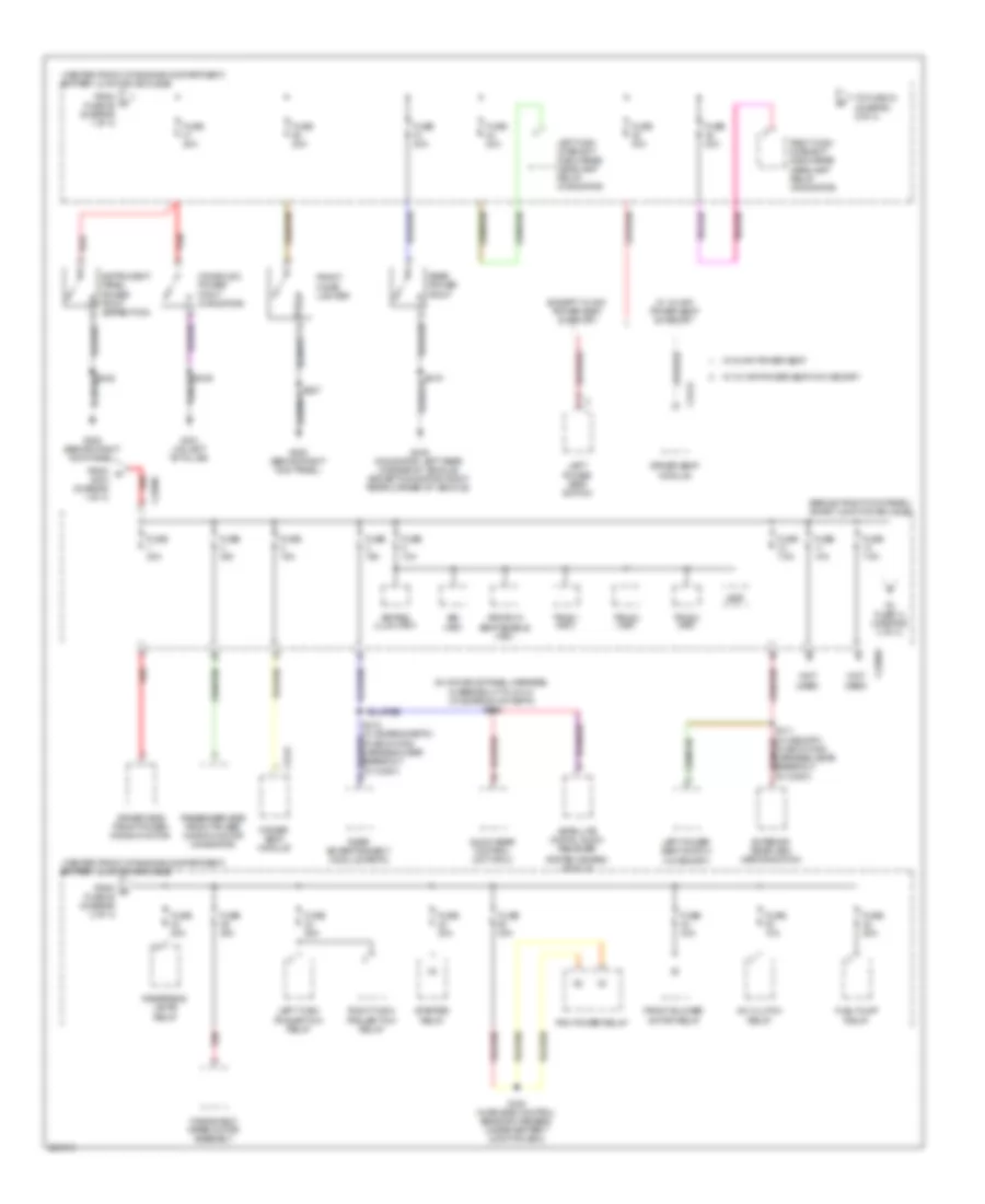
Power Distribution Wiring Diagram (1 of 4) for Ford Expedition 2008

List of elements for Power Distribution Wiring Diagram (1 of 4) for Ford Expedition 2008:
- (center front of engine compartment) battery junction box (bjb)
- (in alternator rectifier system harness, near right front of engine compartment) s145
- (in alternator rectifier system harness, near right front of engine compartment) s146
- (in engine control sensor harness, near breakout to front of engine compartment) s112
- 4x4 control module
- 6r75 automatic transmission (expedition) 6hp26 automatic transmission (navigator)
- Air suspension compressor relay
- Anti-lock brake system (abs) module
- Auxiliary relay box 2 (right rear corner of vehicle)
- Battery
- Battery charge trailer tow relay
- Brake pedal position switch
- C175b
- C2131a
- C281b
- C3265a
- C3313b
- C4174a
- Console 1 power point
- Dual climate controlled seat module (dcsm)
- Evap canister vent solenoid
- From a fuse 7 (diagram 1 of 4)
- From b fuse 29 (diagram 1 of 4)
- Fuse (expedition) 20a
- Fuse 10a
- Fuse 15a
- Fuse 20a
- Fuse 25a
- Fuse 30a
- Fuse 40a
- Fuse 60a
- G107 (right rear of engine compartment)
- G301 (on left "b" pillar)
- Generator
- Harness, in breakout to left side of dash)
- Left third row folding seat relay
- Parking lamp trailer tow relay
- Power fold running board module
- Power liftgate module
- Powertrain control module (pcm)
- Rear blower motor relay 1
- Rear window defrost relay
- Red
- Right power seat switch
- Right third row folding seat relay
- Roof opening panel module (if equipped)
- Run/ start relay
- S102
- S104 red (in engine control sensor harness, near breakout to c140)
- S121 (in engine control sensor harness, under battery junction box)
- S144 (navigation: in alternator rectifier system harness, near right front of engine compartment) (expedition: in alternator rectifier system harness, near breakout to battery)
- S328 (in power seats harness, near breakout to passenger's seat)
- Starter motor
- To fuse 1 (diagram 2 of 4)
- To fuse 31 (diagram 1 of 4)
- To fuse 41 (diagram 2 of 4)
- To fuse 67 (diagram 4 of 4)
- To fuse 8 (diagram 1 of 4)
- To s258 (diagram 4 of 4)
- Trailer electronic brake control module
- Vehicle dynamics module (vdm)
- W/ 10-way power seat
- W/ 6-way power seat
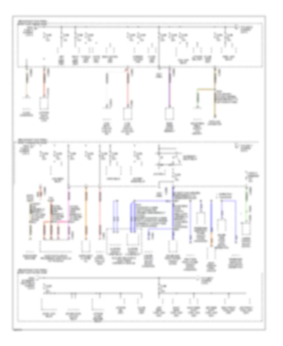
Power Distribution Wiring Diagram (2 of 4) for Ford Expedition 2008
List of elements for Power Distribution Wiring Diagram (2 of 4) for Ford Expedition 2008:
- (behind right kick panel) smart junction box (sjb)
- (center front of engine compartment) battery junction box (bjb)
- (in console panel harness, in breakout to c314) (w/ sdars & w/o retm) s346
- (not used)
- 3rd row seat enable (fet)
- A/c clutch relay
- Audio rear control unit (rcu)
- Bsi (fet)
- C2280c
- C2280e
- C341a
- C341c
- Console 2 power point (navigator)
- Driver seat module
- Driver side front power window motor
- Except 10-way power seat & memory
- Exterior rear view mirror switch
- From d fuse 48 (diagram 2 of 4)
- From fuse 46 (diagram 1 of 4)
- From r s104 (diagram 1 of 4)
- Front blower motor relay
- Front cigar lighter
- Fuel pump relay
- Fuse 10a
- Fuse 15a
- Fuse 20a
- Fuse 25a
- Fuse 30a
- Fuse 40a
- Fuse 7.5a
- G200 (behind right kick panel)
- G301 (on left "b" pillar)
- G402 (navigator: left rear corner of vehicle) (except navigator: right rear corner of vehicle)
- Instrument panel power point (expedition)
- Keypad illum (fet)
- Left high intensity discharge headlamp relay (navigator)
- Left power seat switch
- Left power seat switch (w/ memory)
- Left turn trailer tow relay
- Passenger side front power window motor (navigator)
- Pcm power relay
- Rear entertainment module (retm)
- Rear power point
- Red
- Reversing lamps relay
- Right high intensity discharge headlamp relay (navigator)
- Right turn trailer tow relay
- S120 (in engine control sensor harness, under battery junction box)
- S227
- S419
- Satellite digital audio receiver
- Starter relay
- System (sdars) module
- To fuse 14 (diagram 3 of 4)
- To fuse 33 (diagram 2 of 4)
- Tpms 1 (fet)
- Tpms 2 (fet)
- Tpms 3 (fet)
- Vbat
- W/ 10-way power seat & memory
- W/ 10-way power seat w/o memory
- W/ 6-way power seat
- Windshield wiper motor assembly
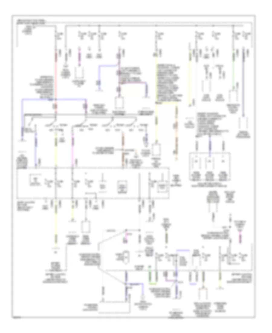
Power Distribution Wiring Diagram (3 of 4) for Ford Expedition 2008
List of elements for Power Distribution Wiring Diagram (3 of 4) for Ford Expedition 2008:
- (behind right kick panel) smart junction box (sjb)
- (in driver's door window regulator harness, in breakout to driver's door) (navigator) s500
- (in main harness, near breakout to center of dash) s247
- (not used)
- Accessory delay relay
- Adjustable pedal switch (w/o memory)
- Audio control module (acm)
- Audio digital signal processing (dsp) module (w/ thx audio)
- Audio- phile audio
- Auxiliary relay box 2 (right rear corner of vehicle)
- Backlighting led (fet)
- Battery saver relay
- C2280e
- C2280f
- C2280g
- C228a
- C2357a
- C2364a
- C240a
- C4174a
- C504a
- C535a
- C535b
- Circuit breaker f47 30a
- Clock (navigator)
- Control
- Data link connector
- Door lock relay
- Driver door unlock relay
- Driver side door lock switch (expedition)
- Driver side front power window motor
- Expedition
- Floor lamp (fet)
- Fog lamp relay
- From s fuse 13 (diagram 2 of 4)
- From t fuse 22 (diagram 3 of 4)
- From u accessory delay relay (diagram 3 of 4)
- Fuse 10a
- Fuse 15a
- Fuse 20a
- Fuse 25a
- High beam relay
- Horn relay
- Hvac (datc) module (automatic a/c)
- Hvac (emtc) module (manual a/c)
- Instrument cluster (ic)
- Interior lighting (fet)
- Left front turn lamp (fet)
- Left low beam (fet)
- Left rear stop/ turn lamp (fet)
- Left rear turn lamp (fet)
- Liftgate glass release relay
- Liftgate rel (fet)
- Liftgate/ trunk module (ltm)
- Master window adjust switch
- Master window adjust switch (navigator)
- Navigator
- Near breakout to passenger's door) s601
- Park lamp relay
- Passenger side door lock switch (expedition)
- Passenger side front power window motor (navigator)
- Puddle lamp (fet)
- Pulse train (fet)
- Quarter window close relay
- Quarter window open relay
- Rear wiper motor assembly
- Red
- Right front turn lamp (fet)
- Right low beam (fet)
- Right rear stop/ turn lamp (fet)
- Right rear turn lamp (fet)
- Right side front power window switch (navigator)
- Roof opening panel module
- S248 (w/o memory) (in main harness, near breakout to left side of dash)
- Subwoofer amplifier
- Thx audio
- To fuse 17 (diagram 3 of 4)
- To fuse 27 (diagram 4 of 4)
- To fuse 38 (diagram 3 of 4)
- White light (fet)
Power Distribution Wiring Diagram (4 of 4) for Ford Expedition 2008
List of elements for Power Distribution Wiring Diagram (4 of 4) for Ford Expedition 2008:
- (behind right kick panel) smart junction box (sjb)
- (except navigator: in rear light connector harness, in breakout to right side of loading space) (navigator: in rear light connector harness, near breakout to auxiliary relay box 2) s417
- (expedition-el & navigator-l: in rear light connector harness, near breakout to c405) (expedition: in rear light connector harness, near breakout to g401) (navigator: in rear light connector harness, near breakout to left side of loading space) (w/ rear view camera) s450
- (expedition: in main harness, near breakout to steering column) (navigator: in main harness, near breakout to auxiliary relay box 1) s257
- (in engine control sensor harness, near breakout to right rear of engine compt)
- (in engine control sensor harness, under battery junction box)
- (in main harness, near breakout to center of dash)
- (not used)
- 4x4 control module
- 6r75 automatic transmission (expedition) 6hp26 automatic transmission (navigator)
- Acc
- Anti-lock brake system (abs) module
- Audio control module (acm)
- Auxiliary relay box 2 (right rear corner of vehicle)
- Battery charge trailer tow relay
- Battery junction box (bjb) (center front of engine compartment)
- C175b
- C2280a
- C2280e
- C2280f
- C2280g
- C228a
- C2357a
- C240a
- C281a
- C310a
- Dimming interior rear view mirror) s911
- Electronic compass
- From fuse 69 (diagram 4 of 4)
- From ignition switch (diagram 4 of 4)
- From run/ start relay (diagram 1 of 4)
- From s114 (diagram 1 of 4)
- From v fuse 6 (diagram 3 of 4)
- Front blower motor relay
- Fuel pump motor diode
- Fuel pump relay
- Fuse 10a
- Fuse 20a
- Fuse 30a
- Fuse 5a
- Fuse 7.5a
- Heated positive crankcase ventilation (pcv) valve
- Hvac (datc) module
- Hvac (eatc) module
- Ignition switch
- Instrument cluster (ic)
- Integrated wheel ends solenoid
- Interior rear view mirror
- Key in ignition
- Key release interlock actuator (w/ floor shifter)
- Lock
- Nca
- Parking aid module (pam)
- Passive anti-theft transceiver
- Powertrain control module (pcm)
- Rear blower motor relay 1
- Rear blower motor relay 2
- Rear blower motor relay 3
- Rear view camera (if equipped)
- Rear view camera display mirror (if equipped)
- Rear wiper motor assembly
- Restraints control module (rcm)
- Run
- Run/ accy
- Run/ start ign switch
- S116
- S154
- S156 (in engine control sensor harness, under battery junction box)
- S258
- Smart junction box (sjb) (behind right kick panel)
- Start
- Start/ run
- Start/ run diode
- Starter relay
- To fuse 30 (diagram 4 of 4)
- To s155 (diagram 4 of 4)
- Windshield wiper motor assembly