POWER DISTRIBUTION
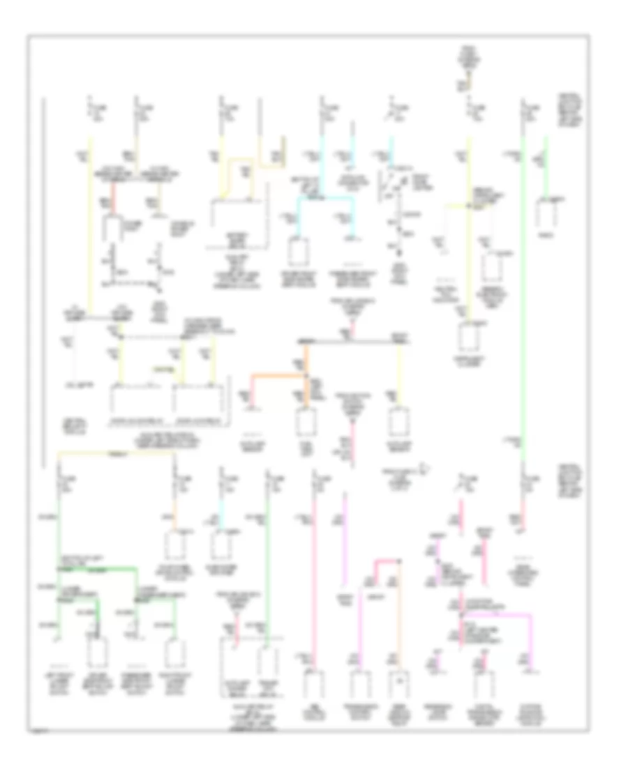
Power Distribution Wiring Diagram (1 of 3) for Ford Explorer Sport Trac 2003

List of elements for Power Distribution Wiring Diagram (1 of 3) for Ford Explorer Sport Trac 2003:
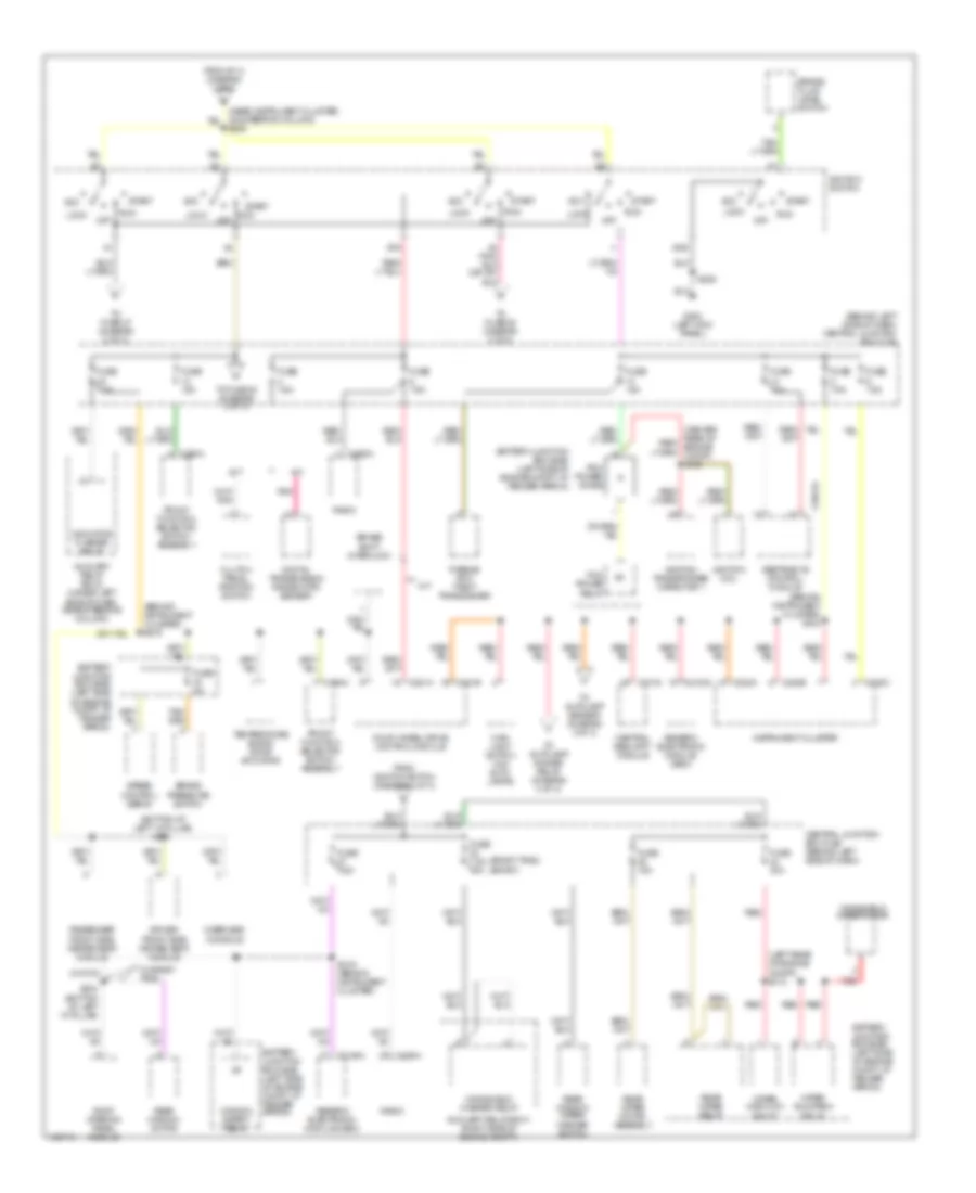
Power Distribution Wiring Diagram (2 of 3) for Ford Explorer Sport Trac 2003
List of elements for Power Distribution Wiring Diagram (2 of 3) for Ford Explorer Sport Trac 2003:
Power Distribution Wiring Diagram (3 of 3) for Ford Explorer Sport Trac 2003
List of elements for Power Distribution Wiring Diagram (3 of 3) for Ford Explorer Sport Trac 2003: