POWER DISTRIBUTION
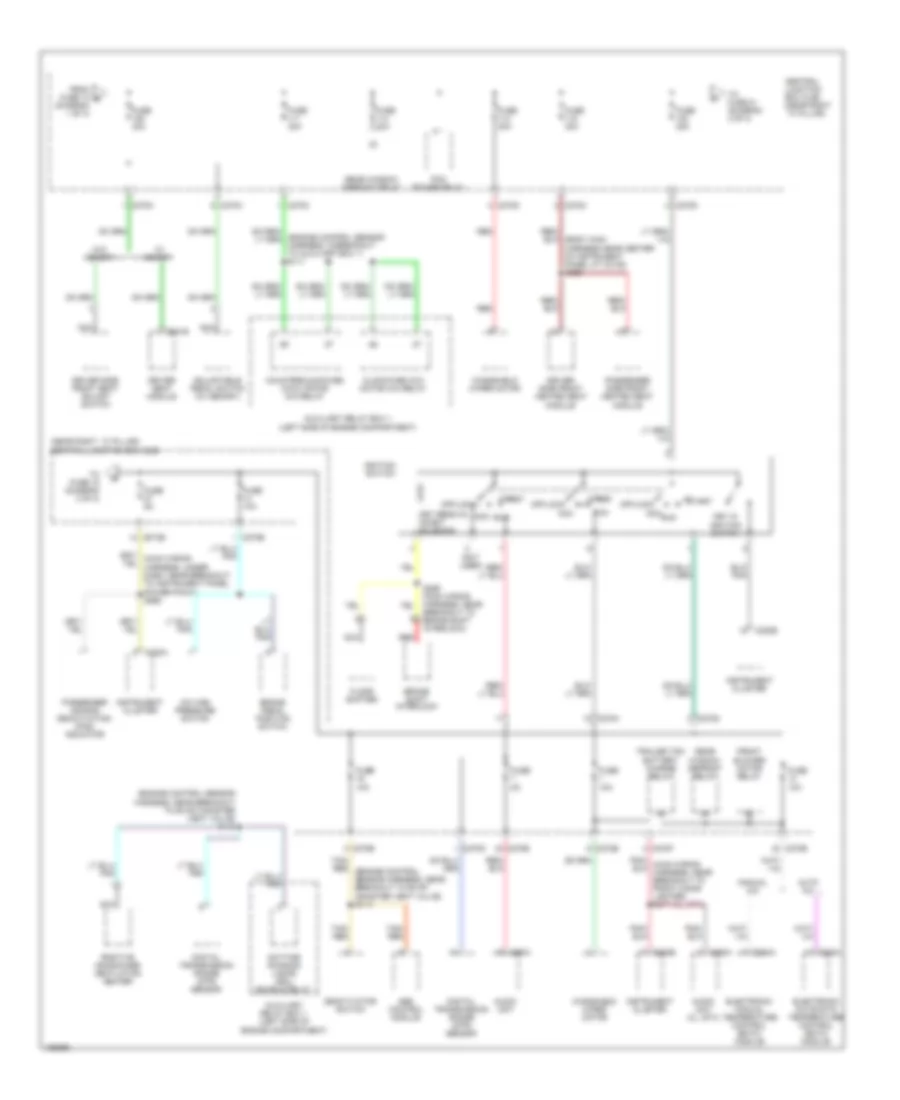
Power Distribution Wiring Diagram (1 of 3) for Ford Pickup F150 2004

List of elements for Power Distribution Wiring Diagram (1 of 3) for Ford Pickup F150 2004:
- (diagram 1 of 3)
- (main wiring harness, near breakout to autolamp/ sunload sensor) (w/ body control module) s266
- (seat control feed jumper harness near right side of instrument panel c3135) s315
- (w/ memory)
- 4x4 center axle disconnect solenoid
- A/c clutch relay
- Abs control module
- Audio unit
- Auto a/c
- Autolamp/ sunload sensor
- Auxiliary relay box 1 (left side of engine compt)
- Battery
- Battery saver relay
- Body control module
- Brake pedal position switch
- C102b
- C175b
- C205a
- C228a
- C270b
- C270c
- C270d
- C270e
- C270f
- C270g
- C270h
- C270j
- C270k
- C270m
- C270n
- C290a
- C294a
- C3008a
- C341c
- Central junction box (cjb) (near right ``a" pillar)
- Console 1 power point
- Console 2 power point
- Data link connector (dlc)
- Driver seat module
- Driver side front seat adjust switch
- Dvd player
- Electronic automatic temperature control (eatc) module
- Electronic manual temperature control (emtc) module
- Exterior rear view mirror switch
- From fuse 5 a
- Front blower motor relay
- Front cigar lighter
- Fuse 10a
- Fuse 15a
- Fuse 20a
- Fuse 25a
- Fuse 30a
- Fuse 40a
- Fuse 5a
- Fuse 7.5a
- G202 (in left front footwell)
- G206 (right kick panel)
- Generator
- Harness wires near center area of roof near subwoofer connector) s328
- Horn relay
- Illumination
- Indicator flasher relay
- Instrument panel power point
- Interior lights system
- Main light switch
- Manual a/c
- Nca
- Of roof at c339) s338
- Passenger side front seat adjust switch
- Powertrain control module (pcm)
- Red
- S120 (alternator rectifier harness, near breakout to fusible link b)
- S201
- S203
- S236
- S345 (w/ memory) (body main harness near right side of instrument panel near inertia fuel shutoff switch)
- S355
- S380
- Sensor harness, near breakout to g102) (w/ 4x4) s105
- Starter motor
- Starter relay
- Subwoofer
- To fuse 109 (diagram 2 of 3)
- To fuse 6 (diagram 1 of 3)
- Trailer electronic brake control module
- Trailer tow battery charge relay
- Trailer tow parking lamp relay
- Trailer tow reversing lamp relay
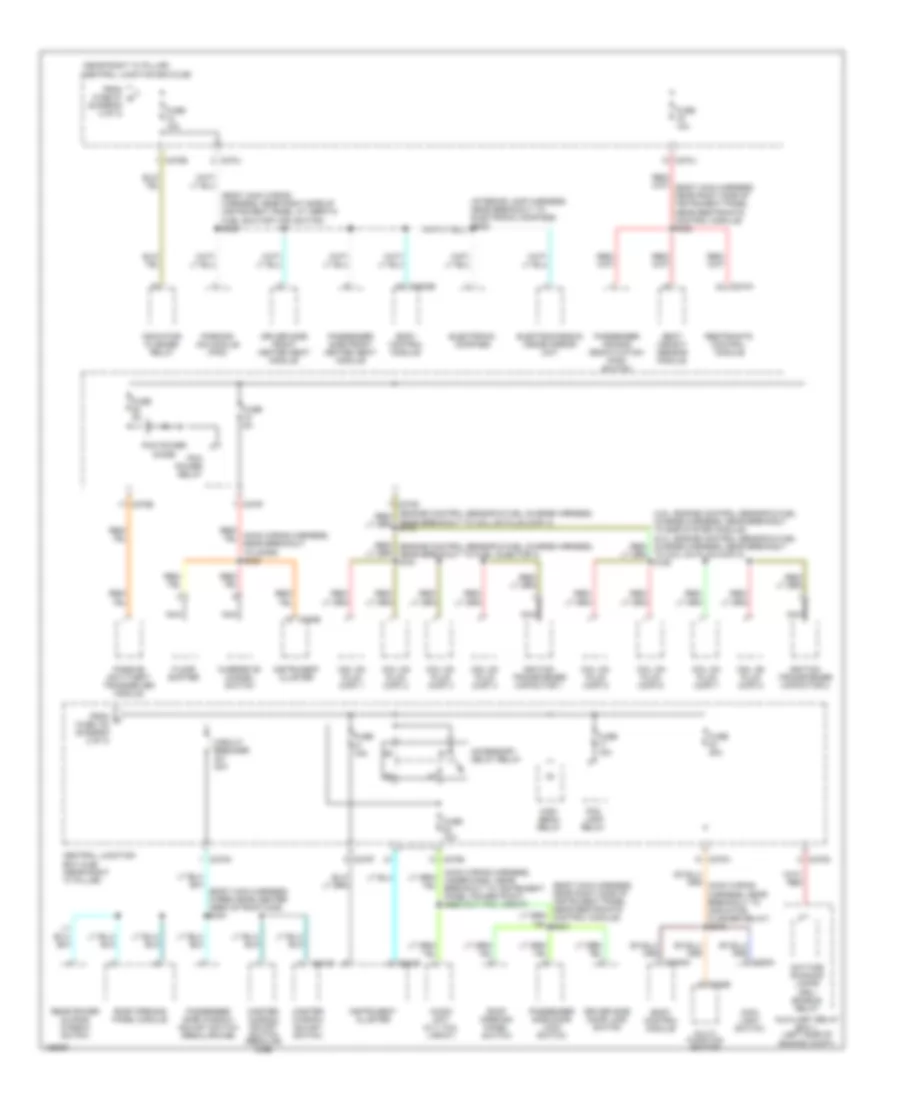
Power Distribution Wiring Diagram (2 of 3) for Ford Pickup F150 2004
List of elements for Power Distribution Wiring Diagram (2 of 3) for Ford Pickup F150 2004:
- (diagram 1 of 3)
- (engine control sensor harness, in breakout to auxiliary box 1) s111
- (engine control sensor harness, near breakout to evap canister vent valve) s112
- (near right ``a" pillar) central junction box (cjb)
- (not used)
- A/c high pressure switch
- Abs control module
- Acc
- Adjustable pedal switch (w/ memory)
- Audio unit
- Audio unit (xl, stx)
- Auto a/c
- Auxiliary relay box 1 (left side of engine compartment)
- Brake pedal position switch
- Brake shift interlock
- C220a
- C220b
- C228a
- C270b
- C270c
- C270d
- C270e
- C270f
- C270g
- C270h
- C270m
- C290a
- C294a
- C341b
- Central junction box (cjb) (near right ``a" pillar)
- Clockwise (cw) motor 4x4 relay
- Counterclockwise (ccw) motor 4x4 relay
- Daytime running lamps (drl) enable relay
- Deactivator switch
- Digital transmission range (dtr) sensor
- Driver seat module
- Driver side front heated seat module
- Driver side front seat adjust switch
- Electronic automatic temperature control (eatc) module
- Electronic manual temperature control (emtc) module
- Floor shifter
- From fuse 10 b
- Front blower motor relay
- Fuse 10a
- Fuse 20a
- Fuse 30a
- Fuse 40a
- Fuse 5a
- Ignition switch
- Instrument cluster
- Key in ignition switch
- Key removal inhibit solenoid
- Manual a/c
- Nca
- Off/lock
- Passenger air bag deactivation (pad) indicator
- Passenger side front heated seat module
- Pcm power relay
- Positive crankcase ventilation heater
- Rear window defrost relay
- Red
- Run
- S299 (main wiring harness, near breakout to brake shift interlock)
- Start
- Tan/ red
- Tan/ red (engine control sensor harness, near breakout to evap canister vent valve) s113
- To fuse 18 (diagram 3 of 3)
- To fuse 21 (diagram 3 of 3)
- Trailer tow battery charge relay
- W/ memory
- W/o memory
- Windshield wiper motor
Power Distribution Wiring Diagram (3 of 3) for Ford Pickup F150 2004
List of elements for Power Distribution Wiring Diagram (3 of 3) for Ford Pickup F150 2004:
- (body main harness wires near center area of roof c339) s344
- (body main wiring harness, near right side of instrument panel at inertia fuel shutoff (ifs) switch) s228
- (diagram 2 of 3)
- (interior lamp harness, near breakout to electronic compass)
- (main wiring harness, under dash, near breakout to instrument panel power point) s285 (xlt, fx4, lariat)
- (near right "a" pillar) central junction box (cjb)
- Accessory delay relay
- Audio unit (xlt, fx4, lariat)
- Auxiliary relay box 1 (left side of engine compt)
- Body control module
- C202b
- C205a
- C220b
- C270d
- C270e
- C270f
- C270h
- C270j
- C270n
- C3008a
- C3008b
- C310a
- C504b
- Central junction box (cjb) (near right "a" pillar)
- Circuit breaker 30a
- Coil on plug (cop) 1
- Coil on plug (cop) 2
- Coil on plug (cop) 3
- Coil on plug (cop) 4
- Coil on plug (cop) 5
- Coil on plug (cop) 6
- Coil on plug (cop) 7
- Coil on plug (cop) 8
- Daytime running lamps (drl) enable relay
- Driver side door lock switch
- Driver side front heated seat module
- Electrochromic inside mirror unit
- Electronic compass
- Floor shifter
- Fog lamp relay
- From c fuse 102 (diagram 2 of 3)
- From fuse 27 d
- Fuse 10a
- Fuse 15a
- Fuse 20a
- Fuse 5a
- High beam relay
- Ignition transformer capacitor 1
- Ignition transformer capacitor 2
- Indicator flasher relay
- Instrument cluster
- Main light switch
- Master window adjust switch
- Master window adjust switch (regular cab)
- Multi- function switch
- Nca
- Near breakout to coil on plug (cop) 4)
- Overdrive cancel switch
- Parking aid module (pam)
- Passenger air bag deactivation (pad) switch
- Passenger side door lock switch
- Passenger side front heated seat module
- Passenger side window adjust switch (regular cab)
- Passive anti-theft transceiver module
- Pcm power diode
- Pcm power relay
- Rear power sliding window switch
- Red/ (engine control sensor & fuel charge harness, near breakout to fuel injector 3) s161
- Restraints control module
- Roof opening panel module
- Roof opening panel switch
- S909
- Seat weight sensor module
- To coil on plug (cop) 8) s162