POWER DISTRIBUTION
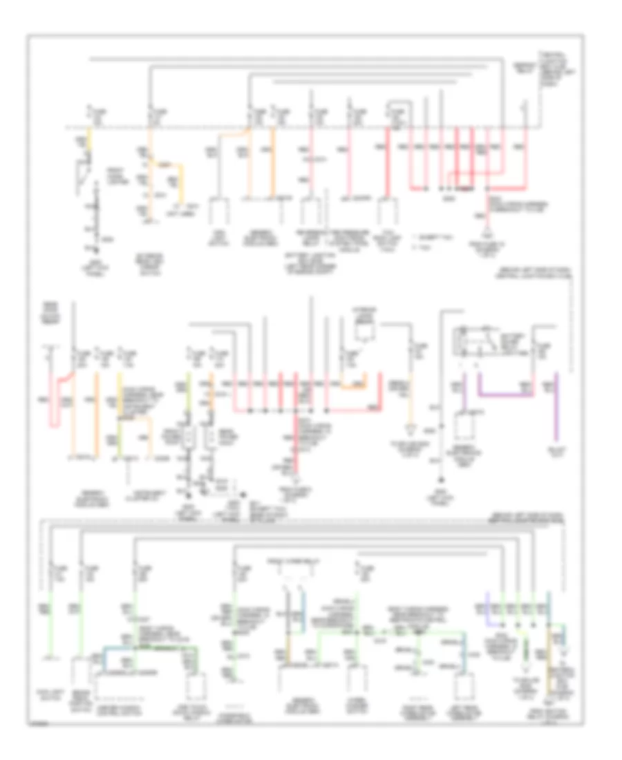
Power Distribution Wiring Diagram (1 of 3) for Ford Transit Connect Electric 2012

List of elements for Power Distribution Wiring Diagram (1 of 3) for Ford Transit Connect Electric 2012:
- (except taxi) left heated winshield relay
- (except taxi) right heated winshield relay
- (info not available)
- (left rear corner of engine compt) battery junction box (bjb)
- (taxi)
- (taxi) auxiliary blower motor assembly
- (tbj2010-tc wiring harness, near breakout to c268) s272
- 1 of 3)
- Abs test connector
- Anti-lock brake system (abs) module
- Auxiliary blower motor relay (taxi)
- Battery
- Block connector
- Blower motor relay
- C1035a
- C1035b
- C1045
- C126
- C175b
- C211
- C213
- C215
- C268
- Central junction box (cjb) (behind left side
- Central junction box (cjb) (behind left side of dash)
- Data link connector (dlc)
- Daytime running lamps relay
- Evap canister vent control solenoid
- Except taxi
- From fuse 3 (diagram 1 of 3)
- From splice s242 (diagram 2 of 3)
- From splice s244 (diagram 3 of 3)
- Fuel pump diode
- Fuel pump relay
- Fuse (taxi) 10a
- Fuse (taxi) 20a
- Fuse (up- fitter) 10a
- Fuse 10a
- Fuse 15a
- Fuse 20a
- Fuse 25a
- Fuse 30a
- Fuse 40a
- Fuse 50a
- Fuse 50a (or 20a)
- G104 (left side of engine compt)
- G105 (left side of engine)
- G200 (left kick panel)
- Generator
- High beam relay
- High speed fan control relay
- Ignition relay
- Inline fuse
- Left heated windshield relay
- Left turn relay
- Low beam interrupt relay
- Low speed fan control relay
- Midi fuse 200a
- Of dash)
- Pcm power relay
- Powertrain control module (pcm)
- Red
- Right heated winshield relay (except taxi)
- Right turn relay
- S118 (dash panel to headlamp junction wiring harness, in under bjb)
- S154
- S205
- S228
- S316
- Starter motor
- Starter relay
- Taxi
- Telematics module
- To block connector (diagram
- To ignition switch (diagram 3 of 3)
- To splice s242 (diagram 2 of 3)
- To splice s243 (diagram 2 of 3)
- To splice s273 (diagram 2 of 3)
- Upfitter
Power Distribution Wiring Diagram (2 of 3) for Ford Transit Connect Electric 2012
List of elements for Power Distribution Wiring Diagram (2 of 3) for Ford Transit Connect Electric 2012:
- (behind left side of dash) central junction box (cjb)
- (body wiring harness, near breakout to c219) s308
- (body wiring harness, near breakout to restraints control module) s305
- (main wiring harness, near breakout to instrument cluster) s235
- (main wiring harness, near breakout to microphone) s231
- (not used)
- 1 of 3)
- Battery junction box (bjb) (left rear corner of engine compt)
- Battery saver relay (upfitter)
- Brake pedal position switch
- C201a
- C201b
- C201c
- C201d
- C201e
- C213
- C219
- C220b
- C237
- C2409a
- C3293a
- C3293b
- C423
- C438
- C510
- C610
- Central
- Cluster (ic)
- Defrost relay
- Except taxi
- Exterior rear view mirror switch
- From fuse 19 (diagram 1 of 3)
- From fuse 9 (diagram
- From ignition relay (diagram 1 of 3)
- Front cigar lighter
- Front power point
- Front wiper relay
- Fuse (taxi) 15a
- Fuse 10a
- Fuse 15a
- Fuse 20a
- Fuse 25a
- Fuse 5a
- Fuse 7.5a
- G200 (left kick panel)
- G200 (taxi) (left kick panel)
- G411 (except taxi) (base of right "d" pillar)
- Generic electronic module (gem)
- Generic electronics module (gem)
- Instrument
- Interior lamps relay
- Junction box (cjb) (behind left side of dash)
- Left rear wiper motor assembly
- Main light switch
- Master window control switch
- Nca
- One touch down window relay
- Rear door unlock relay
- Rear power point
- Red
- Reversing lamps relay
- Right rear wiper motor assembly
- S206
- S228
- S242 (main wiring harness, in breakout to cjb)
- S243 (main wiring harness, in breakout to cjb)
- S273 (main wiring harness, in breakout red
- S315
- Taxi
- Taxi roof lamp switch (taxi)
- Tire pressure monitoring system (tpms) module
- To centeral junction box (cjb) (diagram 1 of 3)
- To cjb) c213
- To splice s202 (diagram 3 of 3)
- To splice s205 (diagram 1 of 3)
- Windshield wiper motor
- Wiper/ washer switch
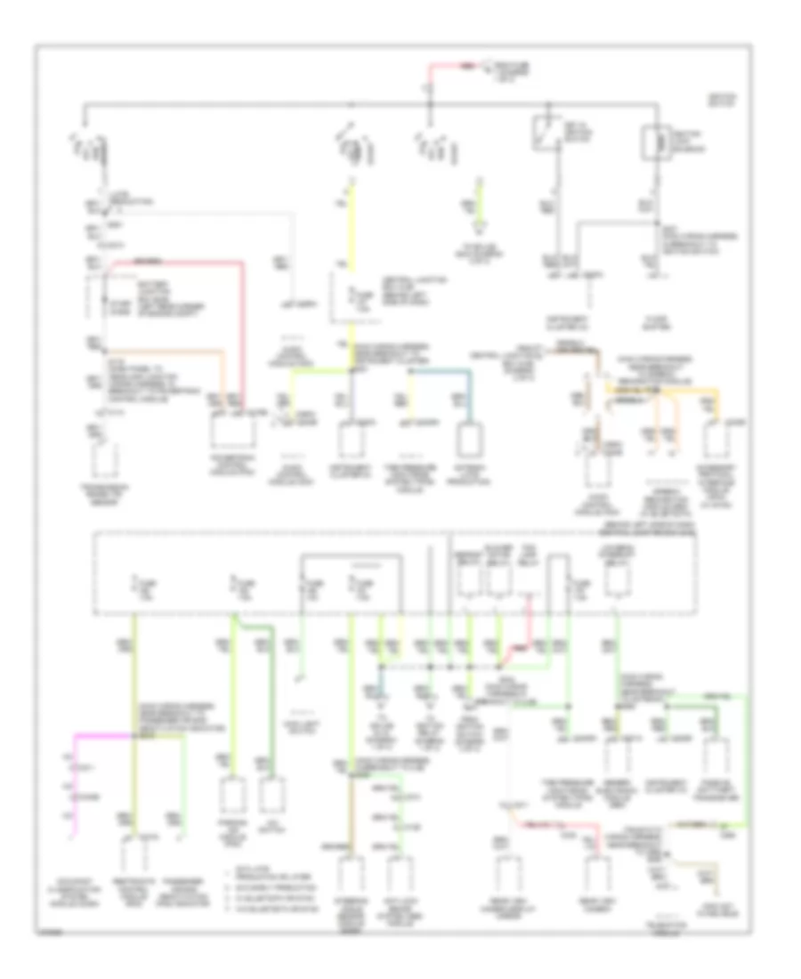
Power Distribution Wiring Diagram (3 of 3) for Ford Transit Connect Electric 2012
List of elements for Power Distribution Wiring Diagram (3 of 3) for Ford Transit Connect Electric 2012:
- (behind left side of dash) central junction box (cjb)
- (info not avaiblable)
- (late production)
- (main wiring harness, near breakout to antenna) s260
- (main wiring harness, near breakout to passenger air bag deactivation indicator) s219
- (main wiring harness, near breakout to speech recognition module)
- (tbj2010-tc wiring harness, near breakout to c268) s250
- 2012 early production
- 2012 late
- A/c switch
- Acc
- Accessory protocol interface module (apim) (w/ sync)
- Antenna (late production)
- Anti-lock brake system (abs) module
- Audio control module (acm)
- Battery junction box (bjb) (left rear corner of engine compt)
- Blower motor relay
- Box (cjb) (diagram 2 of 3)
- C110
- C126
- C175b
- C201a
- C211
- C213
- C220a
- C220b
- C2409a
- C240b
- C268
- C290a
- C290a c240b
- C310a
- C340b
- C438
- Central junction box (cjb) (behind left side of dash)
- Defrost relay
- Floor shifter
- Fog lamp relay
- From central junction l
- From fuse 7 (diagram 1 of 3)
- From ignition switch (diagram 3 of 3)
- Fuse 10a
- Fuse 7.5a
- Generic electronic module (gem)
- Ignition lock solenoid
- Ignition switch
- In breakout to cjb) s280
- Instrument cluster (ic)
- Key in ignition switch
- Low beam interrupt relay
- Main light switch
- Occupant classification system module (ocsm)
- Off
- Parking aid module (pam)
- Passenger air bag deactivation (pad) indicator
- Passive anti-theft transceiver
- Powertrain control module (pcm)
- Production or later
- Rear view camera
- Rear view camera display mirror
- Red
- Restraints control module (rcm)
- Run
- Run acc
- S202
- S237 (main wiring harness, in breakout to ignition switch)
- S244 (main wiring harness,in breakout to cjb)
- S281
- Start
- Start diode
- Steering angle sensor module (sasm)
- Telematics module
- Tire pressure monitoring system (tpms) module
- To ignition relay (diagram 1 of 3)
- To splice s118 (diagram 1 of 3)
- To splice s244 (diagram 3 of 3)
- Transmission range (tr) sensor
- Wiring harness, in breakout to powertrain control module)