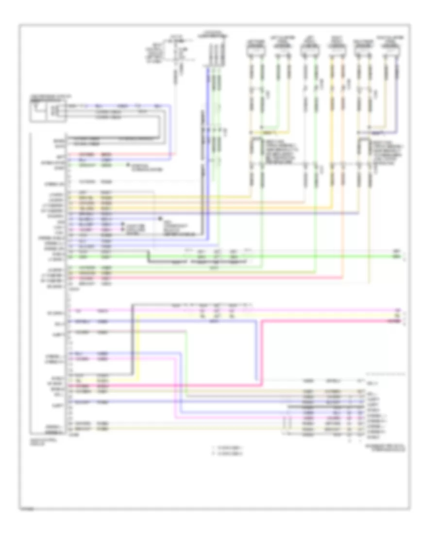
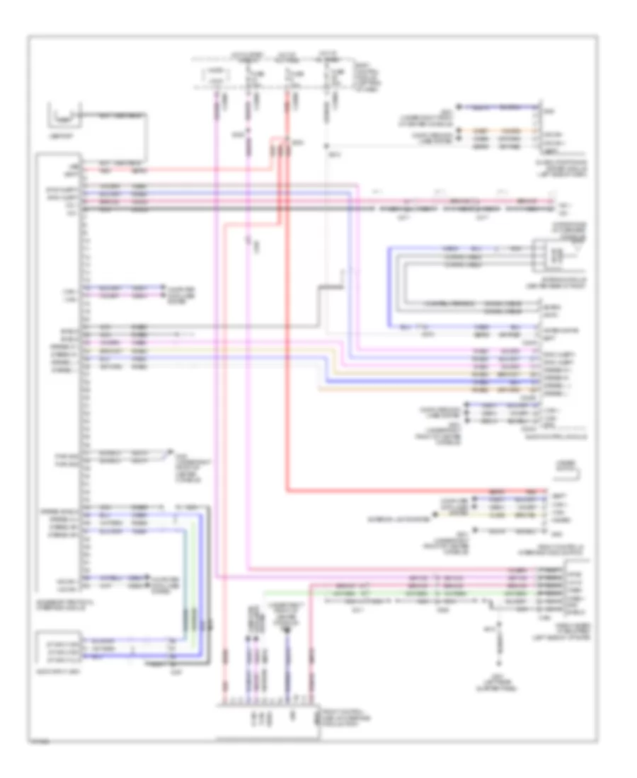
RADIO
Base Radio Wiring Diagram for Ford Explorer Limited 2012

List of elements for Base Radio Wiring Diagram for Ford Explorer Limited 2012:
- (center rear of roof) antenna module
- (w/o sync gen2) front controls/ display interface module
- (w/o sync gen2) s203
- (w/o sync) audio input jack
- A/d channel 2
- A/d channel 3
- A/d channel 4
- A/d return
- Am/fm
- Antenna pwr
- Audio control module
- Batt
- Body control module (left end of dash)
- C210
- C211
- C218b
- C218c
- C2280a
- C2280b
- C237
- C2414a
- C2414d
- C3138
- C3139
- C316
- C327
- Ce336
- Clockspring (top of steering column)
- Cls32
- Coaxial cable
- Computer data lines system
- Dme45
- Front controls interface module
- Fuse 10a
- Fuse 15a
- Fuse 20a
- G201 (under right front of center console)
- Gd214
- Gnd
- Hazard
- Hazard switch
- Hot at all times
- Hs can+
- Hs can-
- I can +
- I can -
- Left front speaker
- Left front tweeter
- Left rear speaker
- Left steering wheel switch
- Lf spkr +
- Lf spkr -
- Logic gnd
- Lr spkr +
- Lr spkr -
- Media
- Micro
- Mute
- Navigation system
- Nca
- Phone
- Ptt
- Red
- Rf spkr +
- Rf spkr -
- Right front speaker
- Right front tweeter
- Right rear speaker
- Right steering wheel switch
- Rme07
- Rme09
- Rme10
- Rme12
- Rme46
- Rmp19
- Rr spkr +
- Rr spkr -
- S211
- Sbp09
- Sbp23
- Sbp29
- Sdars
- Seek +
- Seek -
- Solid state
- St input 2l+
- St input 2r+
- St input 2r-
- Start
- Starting/ charging system
- Steering column control module (top of steering column)
- Stereo 2l+
- Stereo 2r+
- Stereo 2r-
- Stereo shield
- Vbatt
- Vdb04
- Vdb05
- Vdb13
- Vdb14
- Vedio+
- Vedio-
- Vme07
- Vme09
- Vme10
- Vme12
- Vme43
- Vme45
- Vme46
- Vmp19
- Vol +
- Vol -
- W/ satellite radio
- W/ sysc
- W/o sysc
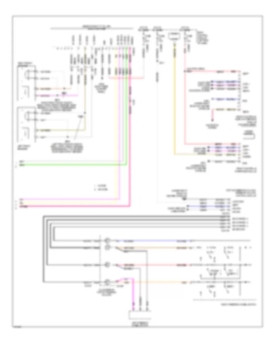
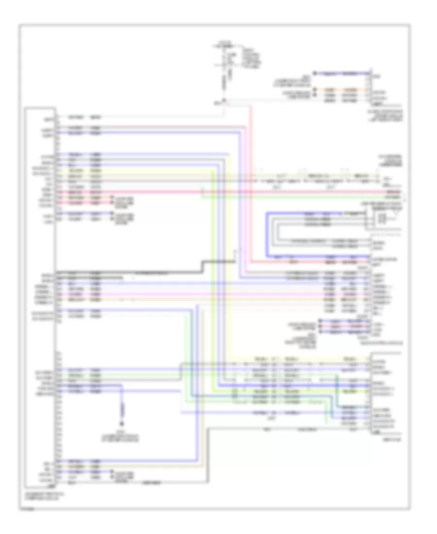
Premium Radio Wiring Diagram (1 of 2) for Ford Explorer Limited 2012
List of elements for Premium Radio Wiring Diagram (1 of 2) for Ford Explorer Limited 2012:
- (body main wiring assembly, near breakout
- (body main wiring assembly, near breakout to
- (center rear of roof) antenna module
- (w/ satellite radio)
- (w/o sync) audio input jack
- Accessory protocol interface module
- Alert+
- Alert-
- Am/fm
- Antenna pwr
- Audio control module
- Batt
- Body control module (left end of dash)
- C210
- C211
- C2280a
- C237
- C240a
- C240b
- C3138
- C3139
- C316
- C327
- Ce336
- Coaxial cable
- Computer data lines system
- Dme17
- Dme18
- Dme45
- Dme52
- Dme80
- Driver's safety belt retractor pretensioner)
- Enable
- Fuse 20a
- G201 (under right front of center console)
- Gd214
- Gnd
- Hot at all times
- I can +
- I can -
- Left front tweeter
- Left quarter panel speaker
- Left rear speaker
- Lf spkr +
- Lf spkr -
- Lf tweeter +
- Lf tweeter -
- Lr spkr +
- Lr spkr -
- Nca
- Rf spkr +
- Rf spkr -
- Rf tweeter +
- Rf tweeter -
- Right front tweeter
- Right quarter panel speaker
- Right rear speaker
- Rme08
- Rme09
- Rme11
- Rme12
- Rme17
- Rme18
- Rme46
- Rme52
- Rme53
- Rme80
- Rr spkr +
- Rr spkr -
- S323
- S326
- Sbp29
- Sdars
- Sdl h
- Sdl l
- Shield
- Sme23
- St input 2l+
- St input 2r+
- St input 2r-
- Start
- Starting/ charging system
- State solid
- Stereo 2l+
- Stereo 2r+
- Stereo 2r-
- Stereo l +
- Stereo l -
- Stereo r +
- Stereo r -
- Stereo shield
- To passenger's load limiting retractor)
- Vdb13
- Vdb14
- Vme08
- Vme09
- Vme11
- Vme12
- Vme17
- Vme18
- Vme43
- Vme45
- Vme46
- Vme52
- Vme53
- Vme80
- Vme90
- Vme91
- W/ sync gen 1
- W/ sync gen 2
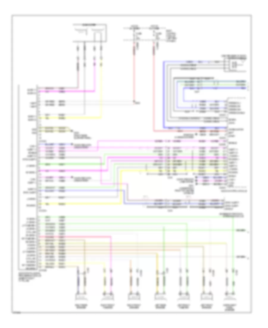
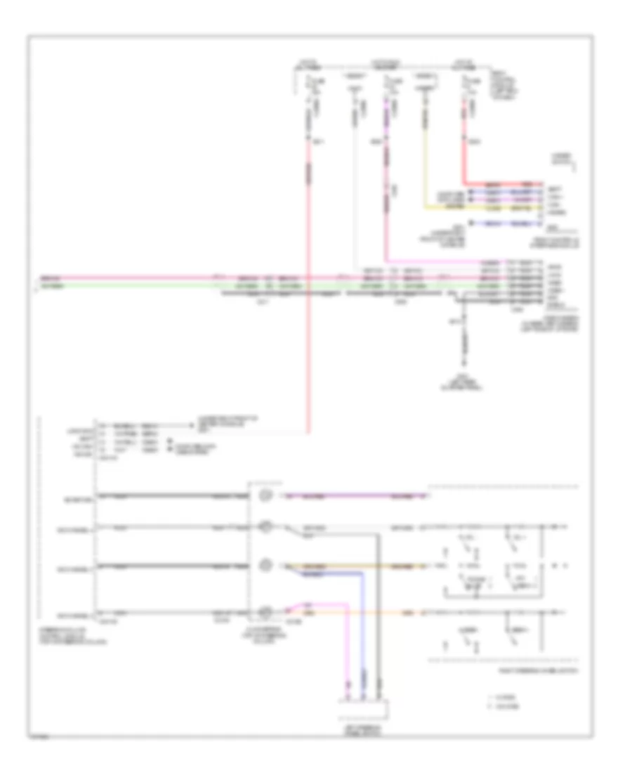
Premium Radio Wiring Diagram (2 of 2) for Ford Explorer Limited 2012
List of elements for Premium Radio Wiring Diagram (2 of 2) for Ford Explorer Limited 2012:
- (base of right "c" pillar) audio amplifier
- (top of steering column) steering column control module
- (under right front of center console) g201
- (w/o sync gen2) s203
- A/d channel 2
- A/d channel 3
- A/d channel 4
- A/d return
- Body control module (left end of dash)
- C210
- C218b
- C218c
- C2280a
- C2280b
- C2280d
- C2414a
- C2414d
- C3138
- C3139
- C3504a
- C3504b
- Clockspring (top of steering column)
- Cls32
- Computer data lines system
- Computer data lines system navigation system
- Enable
- Front controls interface module
- Front controls/ display interface module (w/o sync gen2)
- Fuse 10a
- Fuse 15a
- Fuse 20a
- G201 (under right front of center console)
- G302 (right rear quarter panel)
- Gd214
- Gd348
- Gnd
- Hazard
- Hazard switch
- Hot at all times
- Hs can+
- Hs can-
- I can +
- I can -
- Left front speaker
- Left steering wheel switch
- Lf spkr +
- Lf spkr -
- Logic gnd
- Media
- Micro
- Mute
- Navigation system
- Nca
- Phone
- Ptt
- Red
- Rf spkr +
- Rf spkr -
- Right front speaker
- Right steering wheel switch
- Rme07
- Rme10
- Rme17
- Rme18
- Rmp19
- S211
- S502 (left front door window regulator wiring harness, near breakout to driver's door side impact sensor)
- S503
- S603 (right front door window regulator wiring harness, near breakout to front passenger's door side impact sensor)
- S605
- Sbp05
- Sbp09
- Sbp23
- Seek +
- Seek -
- Sme23
- Vbatt
- Vdb04
- Vdb05
- Vdb13
- Vdb14
- Vedio+
- Vedio-
- Vme07
- Vme10
- Vme17
- Vme18
- Vmp19
- Vol +
- Vol -
- W/ sysc
- W/o sysc
SONY Radio Wiring Diagram (1 of 2) for Ford Explorer Limited 2012
List of elements for SONY Radio Wiring Diagram (1 of 2) for Ford Explorer Limited 2012:
- (center rear of roof) antenna module
- (w/ satellite radio)
- Accessory protocol interface module
- Alert 1+
- Alert 1-
- Alert 2+
- Alert 2-
- Am/fm
- Antenna pwr
- Audio control module
- Audio digital signal processing module (base of right "c" pillar)
- Batt
- Body control module (left end of dash)
- C210
- C2280a
- C2280d
- C237
- C240a
- C240b
- C3138
- C3139
- C3154a
- C3154b
- C3154c
- C316
- C327
- Ce336
- Coaxial cable
- Computer data lines system
- D pillar -
- D pillar+
- Dme17
- Dme45
- Dme80
- Enable
- Fuse 20a
- G201 (under right front of center console)
- G302 (right rear quarter panel)
- Gd214
- Gd348
- Gnd
- Hot at all times
- I can +
- I can -
- Instrument panel speaker
- Ip spkr +
- Ip spkr -
- Left front speaker
- Left front tweeter
- Left rear speaker
- Lf spkr +
- Lf spkr -
- Lf tweeter +
- Lf tweeter -
- Lr spkr +
- Lr spkr -
- Nca
- Rf spkr +
- Rf spkr -
- Rf tweeter +
- Rf tweeter -
- Right front speaker
- Right front tweeter
- Right rear speaker
- Rme01
- Rme02
- Rme06
- Rme07
- Rme08
- Rme09
- Rme10
- Rme11
- Rme12
- Rme17
- Rme18
- Rme39
- Rme46
- Rme80
- Rr spkr +
- Rr spkr -
- S332
- Sbp05
- Sbp29
- Sdars
- Shield
- Sme23
- Solid state
- Start
- Starting/ charging system
- Stereo 2l+
- Stereo 2r+
- Stereo 2r-
- Stereo shield
- Subw 1+
- Subw 1-
- Subw 2+
- Subw 2-
- Subwoofer
- Sync alert+
- Sync alert-
- V batt
- Vdb13
- Vdb14
- Vme01
- Vme02
- Vme06
- Vme07
- Vme08
- Vme09
- Vme10
- Vme11
- Vme12
- Vme17
- Vme18
- Vme39
- Vme43
- Vme45
- Vme46
- Vme80
- Vme92
- Vme93
- Vme94
- Vme95
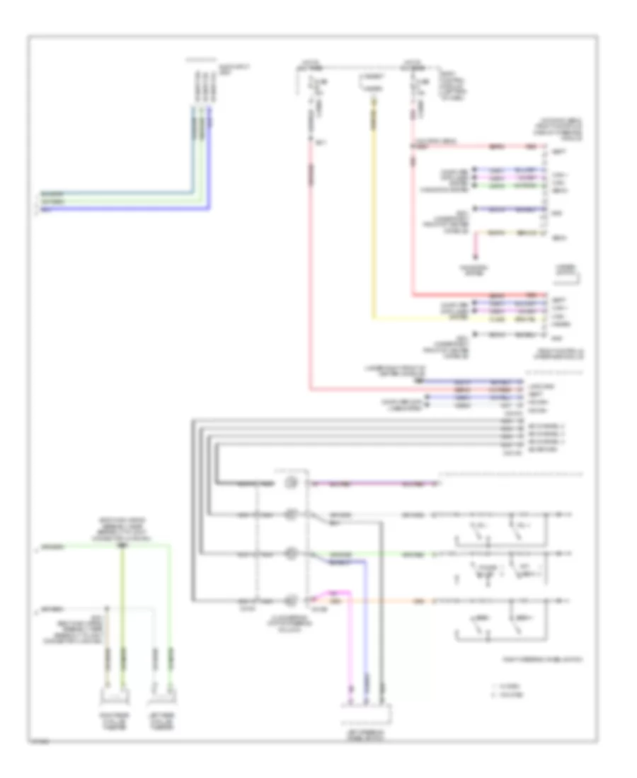
SONY Radio Wiring Diagram (2 of 2) for Ford Explorer Limited 2012
List of elements for SONY Radio Wiring Diagram (2 of 2) for Ford Explorer Limited 2012:
- (body main wiring assembly, near breakout to joint
- (under right front of center console) g201
- (w/o sync gen2) front controls/ display interface module
- (w/o sync gen2) s203
- A/d channel 2
- A/d channel 3
- A/d channel 4
- A/d return
- Audio input jack
- Body control module (left end of dash)
- C218b
- C218c
- C2280a
- C2280b
- C2414a
- C2414d
- Clockspring (top of steering column)
- Cls32
- Computer data lines system
- Connector 4 (hs-can)) s330
- Front controls interface module
- Fuse 10a
- Fuse 15a
- G201 (under right front of center console)
- Gd214
- Gnd
- Hazard
- Hazard switch
- Hot at all times
- Hs can+
- Hs can-
- I can +
- I can -
- Left rear d-pillar tweeter
- Left steering wheel switch
- Logic gnd
- Media
- Micro
- Mute
- Navigation system
- Nca
- Phone
- Ptt
- Red
- Right rear d-pillar tweeter
- Right steering wheel switch
- Rmp19
- S211
- S331 (body main wiring assembly, near breakout to joint connector 4 (hs-can))
- Sbp09
- Sbp23
- Seek +
- Seek -
- St input 2l+
- St input 2r+
- St input 2r-
- Vbatt
- Vdb04
- Vdb05
- Vdb13
- Vdb14
- Vedio+
- Vedio-
- Vmp19
- Vol +
- Vol -
- W/ sysc
- W/o sysc
SYNC Radio Wiring Diagram, with SYNC GEN 1 for Ford Explorer Limited 2012
List of elements for SYNC Radio Wiring Diagram, with SYNC GEN 1 for Ford Explorer Limited 2012:
- (under right front of center console) g201
- (w/ satellite radio)
- Accessory protocol interface module
- Am/fm
- Antenna module (center rear of roof)
- Antenna pwr
- Audio control module
- Audio input jack
- Batt
- Body control module (left end of dash)
- C210
- C211
- C2280a
- C2280b
- C2280c
- C2280d
- C237
- C240a
- C240b
- C317
- C494
- C935
- Cls32
- Coaxial cable
- Computer data lines system
- Dme45
- Dme52
- Dme80
- Dmm23
- Exterior lights system
- Front control/ display interface module (fdim)
- Front controls interface module (pcim)
- Fuse 10a
- Fuse 20a
- G201 (under right front of center console)
- G301 (left rear quarter panel)
- Gd214
- Global positioning system module (left side of dash)
- Gnd
- Hazard
- Hazard switch
- Hot at all times
- Hot in start or run
- Hs can +
- Hs can -
- I can +
- I can -
- Lin 03
- Mic +
- Mic -
- Micro
- Microphone (in overhead console)
- Ms can +
- Ms can -
- Nca
- Pwr gnd
- Red
- Rme46
- Rme52
- Rme53
- Rme80
- Rmp19
- S203
- S212
- S410
- Sbp09
- Sbp29
- Sdars
- Shield
- St input 2l+
- St input 2r+
- St input 2r-
- State solid
- Stereo 2l+
- Stereo 2r+
- Stereo 2r-
- Stereo l +
- Stereo l -
- Stereo r +
- Stereo r -
- Stereo shield
- Sync alert+
- Sync alert-
- Usb
- Usb cable
- Usb port
- Vbatt
- Vdb04
- Vdb05
- Vdb06
- Vdb07
- Vdb13
- Vdb14
- Video camera (if equipped) (left side of liftgate)
- Video+
- Video-
- Vme43
- Vme45
- Vme46
- Vme52
- Vme53
- Vme80
- Vmm23
- Vmp19
- Vpwr
SYNC Radio Wiring Diagram, with SYNC GEN 2 (1 of 2) for Ford Explorer Limited 2012
List of elements for SYNC Radio Wiring Diagram, with SYNC GEN 2 (1 of 2) for Ford Explorer Limited 2012:
- (center rear of roof) antenna module
- (in overhead console) microphone
- (w/ premium audio)
- (w/ satellite radio)
- 5v pwr
- Accessory protocol interface module
- Alert+
- Alert-
- Am/fm
- Antenna pwr
- Audio control module
- Aux audio l+
- Aux audio l-
- Aux audio r+
- Aux audio r-
- Aux video+
- Aux video-
- Batt
- Body control module (left end of dash)
- C210
- C211
- C2280a
- C237
- C240a
- C240b
- C317
- Coaxial cable
- Computer data lines system
- Dme45
- Dme52
- Dme80
- Dme88
- Dmm23
- Fuse 20a
- G201 (under right front of center console)
- Gd214
- Global positioning system module (left side of dash)
- Gnd
- Hot at all times
- Hs can +
- Hs can -
- I can +
- I can -
- Lme89
- Media gnd
- Media hub
- Mic +
- Mic -
- Ms can +
- Ms can -
- Nca
- Pwr gnd
- Rme45
- Rme46
- Rme52
- Rme53
- Rme80
- Rme88
- Rme89
- Rmp19
- S212
- Sbp29
- Sdars
- Sdl h
- Sdl l
- Shield
- State solid
- Stereo l +
- Stereo l -
- Stereo r +
- Stereo r -
- Usb
- Usb cable
- Vbatt
- Vdb04
- Vdb05
- Vdb06
- Vdb07
- Vdb13
- Vdb14
- Video +
- Video -
- Vme43
- Vme45
- Vme46
- Vme52
- Vme53
- Vme80
- Vme88
- Vme90
- Vme91
- Vmm23
- Vmp19
SYNC Radio Wiring Diagram, with SYNC GEN 2 (2 of 2) for Ford Explorer Limited 2012
List of elements for SYNC Radio Wiring Diagram, with SYNC GEN 2 (2 of 2) for Ford Explorer Limited 2012:
- (under right front of center console) g201
- A/d channel 2
- A/d channel 3
- A/d channel 4
- A/d return
- Body control module (left end of dash)
- C211
- C218b
- C218c
- C2280a
- C2280b
- C2280c
- C2280d
- C2414a
- C2414d
- C494
- C935
- Clockspring (top of steering column)
- Cls32
- Computer data lines system
- Front controls interface module
- Fuse 10a
- Fuse 15a
- G201 (under right front of center console)
- G301 (left rear quarter panel)
- Gd214
- Gnd
- Hazard
- Hazard switch
- Hot at all times
- Hot in run or start
- Hs can+
- Hs can-
- I can +
- I can -
- Left steering wheel switch
- Lin 03
- Logic gnd
- Media
- Micro
- Mute
- Nca
- Phone
- Ptt
- Red
- Right steering wheel switch
- S203
- S211
- S328
- S410
- Sbp09
- Sbp23
- Seek +
- Seek -
- Shield
- Steering column control module (top of steering column)
- Vbatt
- Vdb04
- Vdb05
- Vdb13
- Vdb14
- Video camera (w/ rear view camera) (left side of liftgate)
- Video+
- Video-
- Vol +
- Vol -
- Vpwr
- W/ sysc
- W/o sysc