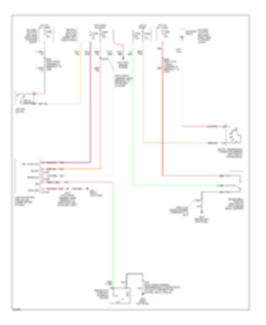
SHIFT INTERLOCK
Shift Interlock Wiring Diagram for Ford Crown Victoria 2010
List of elements for Shift Interlock Wiring Diagram for Ford Crown Victoria 2010:
- (body main wiring harness, in breakout to g212)
- (main wiring harness, near breakout to instrument cluster)
- Anti-lock brakes system
- Automatic temperature control (eatc) module)
- Battery junction box (bjb) (right side of engine compt)
- Brake pedal position (bpp) switch (top of brake pedal support)
- Brake shift interlock (steering column)
- Brake sw
- Bsi
- C2145a
- C2145b
- Central junction box (cjb) (under left side of dash)
- Digital transmission range (dtr) sensor (left side of transmission)
- Fuse 10a
- Fuse 20a
- Fuse 30a
- Fuse 5a
- Fuse 7.5a
- G201 (right kick panel)
- G204 (right kick panel)
- G212 (behind left kick panel)
- Hot at all times
- Hot in run or start
- Hot in start
- Ignition switch
- Key in ignition
- Key-in ignition
- Lighting control module (lcm) (under center of dash)
- Logic gnd
- Red
- Run/st
- S200 (main wiring harness, in breakout to c260)
- S210 (main wiring harness, near breakout to right footwell courtesy light)
- S246 (body main wiring harness, in breakout to c248)
- S267
- S276
- Starter relay
 English