SHIFT INTERLOCK
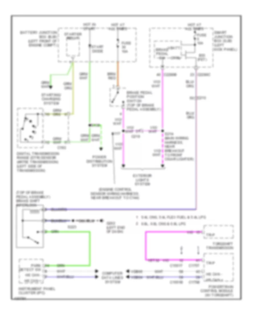
Shift Interlock Wiring Diagram for Ford E-150 XL 2014
List of elements for Shift Interlock Wiring Diagram for Ford E-150 XL 2014:
- (engine control sensor wiring harness, near breakout to c144)
- (top of brake pedal assembly) brake shift interlock
- 5.4l cng, 5.4l flex fuel & 5.4l lpg
- 6.8l, 6.8l cng & 6.8l lpg
- Battery junction box (bjb) (left front of engine compt)
- Brake pedal position switch (top of brake pedal assembly)
- Brake pedal sw
- Bsi (fet)
- C1551b
- C1551t
- C175b
- C175t
- C192
- C210
- C219
- C2280b
- C2280c
- Computer data lines system
- Ctrl
- Detect sw
- Digital transmission range (dtr) sensor (4r75e transmission) (left side of transmission)
- Exterior lights system
- Fuse 10a
- G202 (left end of dash)
- Hot at all times
- Hot in start
- Hs can +
- Hs can -
- Instrument panel cluster (ipc)
- P r
- Park
- Power distribution system
- Powertrain control module (w/ torqshift)
- S117
- S139
- S214 (main wiring harness, near breakout to front cigar lighter)
- S223
- Smart junction box (sjb) (left kick panel)
- Start diode
- Starter relay
- Starting/ charging system
- Torqshift transmission
- Tr-p
- Vbatt
- Vdb04
- Vdb05
- Vet32
 English