SHIFT INTERLOCK
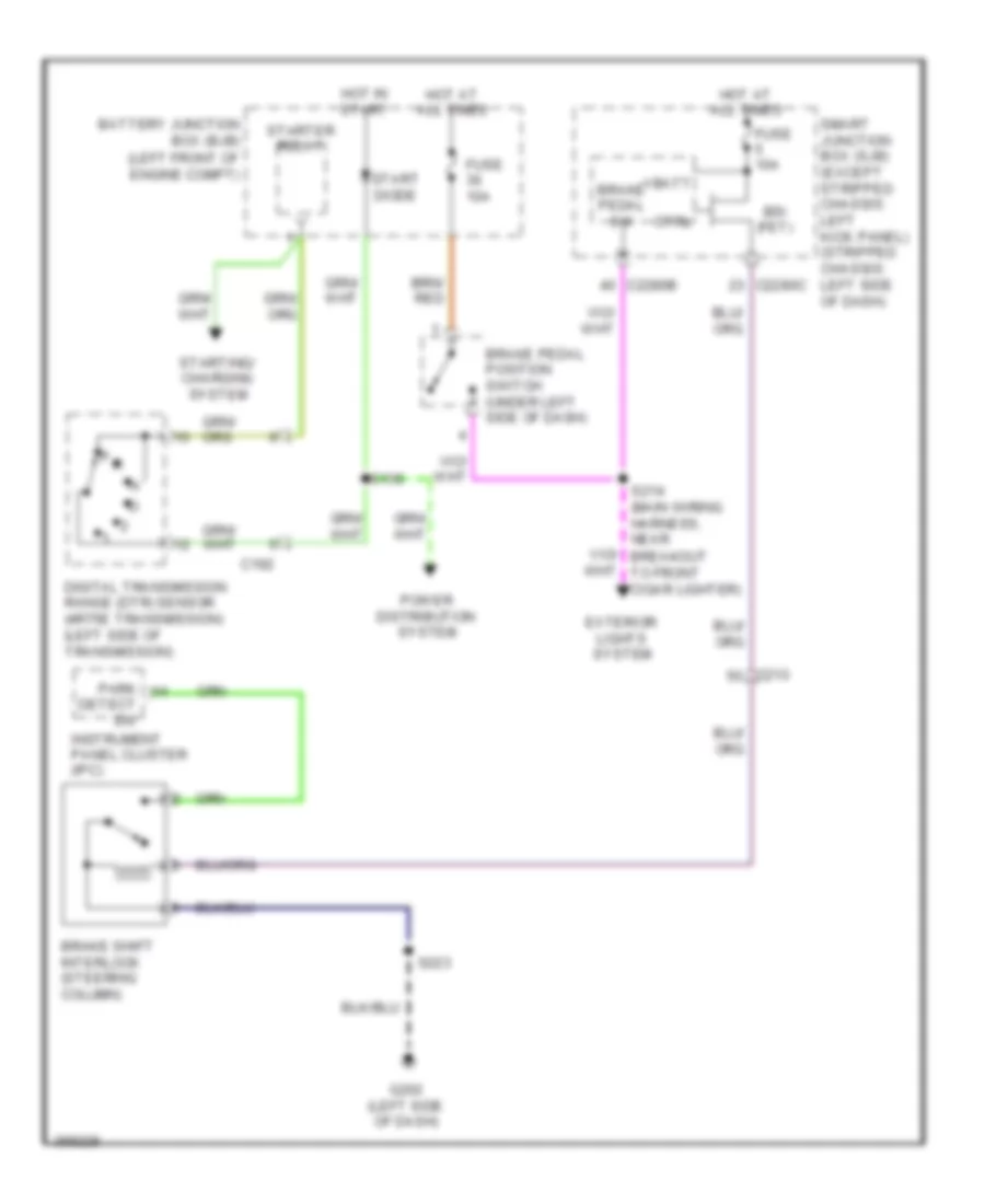
Shift Interlock Wiring Diagram for Ford E-150 XLT 2013
List of elements for Shift Interlock Wiring Diagram for Ford E-150 XLT 2013:
- (left front of engine compt)
- Battery junction box (bjb)
- Brake pedal position switch (under left side of dash)
- Brake pedal sw
- Brake shift interlock (steering column)
- Bsi (fet)
- C192
- C210
- C2280b
- C2280c
- Ctrl
- Detect sw
- Digital transmission range (dtr) sensor (4r75e transmission) (left side of transmission)
- Exterior lights system
- Fuse 10a
- G202 (left side of dash)
- Hot at all times
- Hot in start
- Instrument panel cluster (ipc)
- P r
- Park
- Power distribution system
- S139
- S214 (main wiring harness, near breakout to front cigar lighter)
- S223
- Smart junction box (sjb) (except stripped chassis: left kick panel) (stripped chassis: left side of dash)
- Start diode
- Starter relay
- Starting/ charging system
- Vbatt
 English