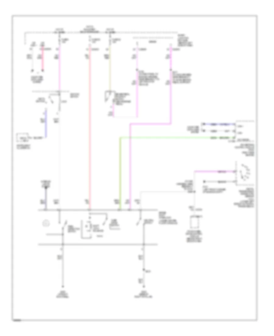
SHIFT INTERLOCK
Shift Interlock Wiring Diagram for Ford Explorer Sport Trac 2008
List of elements for Shift Interlock Wiring Diagram for Ford Explorer Sport Trac 2008:
- (in main harness, near breakout to c215) s200
- (under center floor console)
- All times
- Brake pedal position switch (above brake pedal)
- Brake shift interlock
- C175b
- C2280c
- C2280d
- C2280e
- C281a
- Can +
- Can -
- Cet34
- Computer data lines system
- Digital transmission range (dtr) sensor (4.0l) (lower left side of automatic transmission)
- Four-wheel drive control module (behind right side of dash)
- Fuse 20 10a
- Fuse 22 15a
- Fuse 8 15a
- G101 (left front corner of engine compt)
- G200 (at right kick panel)
- G302 (base of right "b" pillar)
- Hot at
- Hot w/
- Ignition switch
- Instrument cluster (ic)
- Interior lights system
- Key in ignition
- Key in sw
- Lock
- Ms can +
- Ms can -
- Neutral switch
- Od cancel
- Over drive switch
- Park detection switch
- Powertrain control module (pcm) (right side engine)
- Run/start relay energized
- S128 (in dash panel to engine harness, near breakout to left front of vehicle)
- S217 (in main harness, near breakout to accelerator pedal support)
- S219
- Sense
- Shift lock solenoid
- Smart junction box (sjb) (behind left side of dash)
- Vdb04
- Vdb05
 English