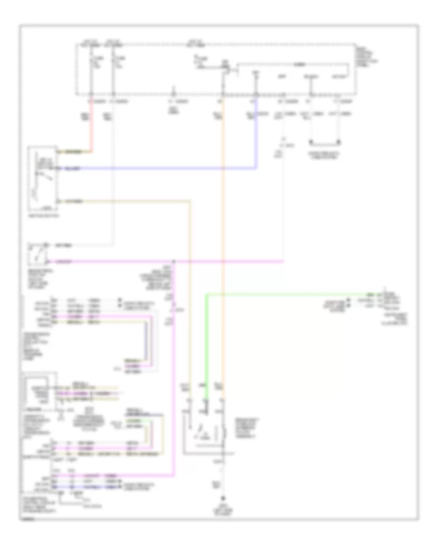
SHIFT INTERLOCK
Shift Interlock Wiring Diagram for Ford F-350 Super Duty Lariat 2013
List of elements for Shift Interlock Wiring Diagram for Ford F-350 Super Duty Lariat 2013:
- (not used)
- (or re406)
- 6.2l
- 6.2l & 6.7l
- 6.7l
- 6.8l
- 6.8l & 6.2l
- Body control module (right kick panel)
- Bpp
- Brake pedal position switch (left side of dash)
- Brake shift interlock (steering column assembly)
- Bsi (fet)
- C1232b
- C175b
- C175t
- C210
- C212
- C2280a
- C2280b
- C2280c
- C2280d
- C2280f
- Ccb08
- Cet22
- Computer data lines system
- Detect
- Fuse 10a
- Fuse 15a
- G203 (left side of dash)
- Hot at all times
- Hs can+
- Hs can-
- Ignition switch
- In park
- Instrument panel cluster (ipc)
- Key in
- Key in ignition switch
- Le111
- Lock
- Micro
- Nca
- Park
- Powertrain control module (right rear of engine compt)
- Ret24
- S184 (6.8l) (transmission wiring harness, near breakout to c145)
- S207 (body main wiring harness, in breakout to behind left side of dash)
- Sigrtn/ trgnd vpwr
- Sigrtn/trgnd
- Torshift 6 transmission (6.2l & 6.7l) torshift transmission (6.8l)
- Transmission control module (tcm) (6.7l) (rear of transfer case)
- Trgnd
- Trp
- Trs/trp
- Vbpwr
- Vdb04
- Vdb05
 English