SUPPLEMENTAL RESTRAINTS
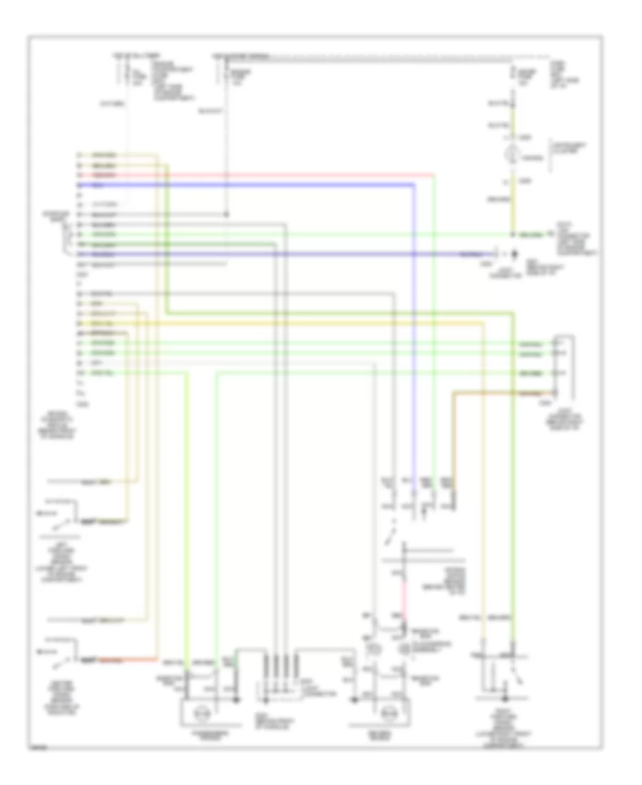
Supplemental Restraint Wiring Diagram for Ford Aspire SE 1994
List of elements for Supplemental Restraint Wiring Diagram for Ford Aspire SE 1994:
- Air bag
- Air bag diagnostic module (behind front of console)
- Air bag safing sensor (behind center of i/p)
- Assembly
- C209
- C221
- C222
- C223
- C224
- Center forward crash sensor (forward of radiator)
- Clockspring
- Dash fuse box (left side of i/p)
- Data link connector (left side of engine compartment)
- Driver's air bag
- Engine compartment fuse box (left side of engine compartment)
- Engine fuse 10a
- G201 (behind right side of i/p)
- G302 (behind front of console)
- Hot at all times
- Hot in start or run
- Inj fuse 30a
- Instrument cluster
- Joint connector
- Joint connector (behind right side of i/p)
- Left forward crash sensor (lower left front of engine compartment)
- Meter fuse 15a
- Nca
- Passenger's air bag
- Red
- Right forward crash sensor (lower right front of engine compartment)
- Shorting bar
 English