SUPPLEMENTAL RESTRAINTS
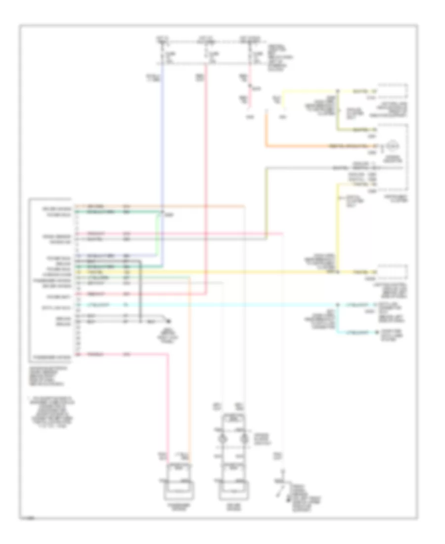
Supplemental Restraint Wiring Diagram for Ford Crown Victoria Police Interceptor 1999
List of elements for Supplemental Restraint Wiring Diagram for Ford Crown Victoria Police Interceptor 1999:
- (analog)
- (analog) (digital)
- (behind left side of dash)
- (digital)
- (main harn, near breakout to instrument cluster) s284
- Air bag electronic crash sensor (behind right side of dash, above glove box)
- Air bag ind
- Air bag indicator
- Air bag sliding contact
- Analog cluster only
- C124
- C2021
- C2026
- C250
- C251
- C255
- C256
- Central junction box (below dash, left of steering column)
- Computer data lines system
- Connector (dlc)
- Crash sensor
- Data link
- Data link (dlc)
- Digital cluster only
- Driver air bag
- Front crash sensor (on left front side of upper radiator support)
- Fuse 10a
- Fuse 15a
- G203 (behind right kick panel)
- Gas
- Ground
- Hot at all times
- Hot in run
- Hot in run or start
- Instrument cluster
- Lighting control module (lcm) (behind left side of dash)
- Natural gas vehicle module (front of radiator support)
- Nca
- Ngv
- Passenger air bag
- Pin shorting bar is engaged when module connector is disconnected (shorting bar is connected between the following pins: 1-15, 7-21, 14-28)
- Power (bat)
- Power (run)
- S269
- S271 (dash harn, near breakout to data link connector)
- S276
- S299 (main harn, near breakout to instrument cluster)
- Shorting bar
- Warning chime
 English