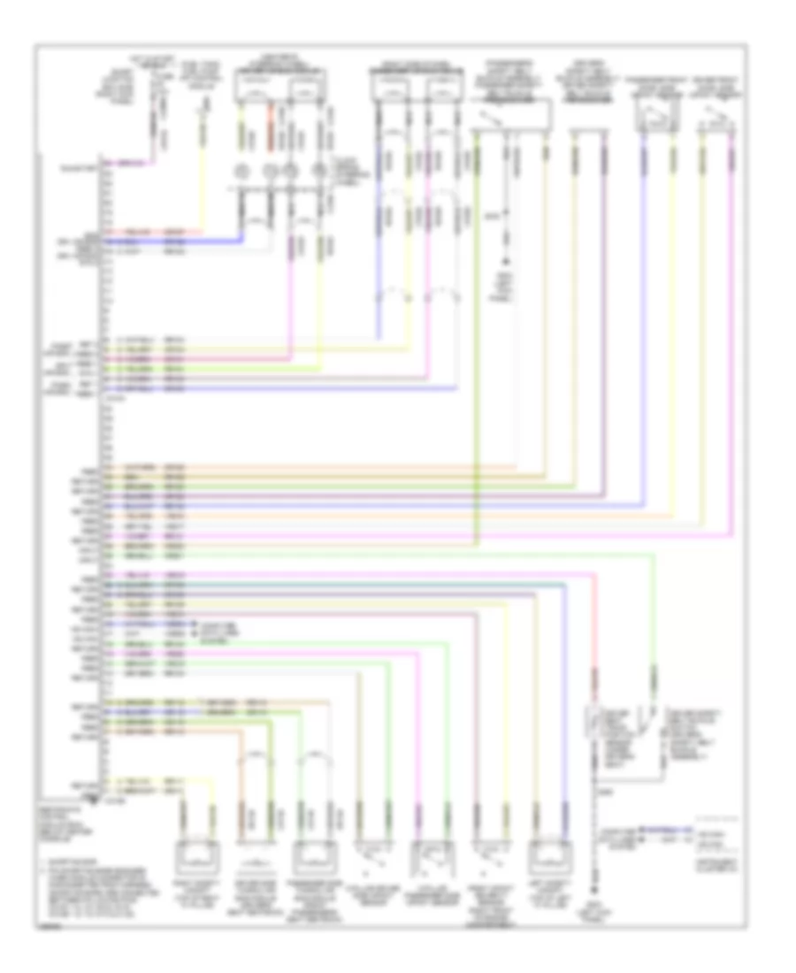
SUPPLEMENTAL RESTRAINTS
Supplemental Restraints Wiring Diagram for Ford Expedition EL 2009
List of elements for Supplemental Restraints Wiring Diagram for Ford Expedition EL 2009:
- (center of steering wheel) driver air bag module
- (driver's safety belt buckle assembly) driver safety belt buckle pretensioner
- (fuel tank) fuel pump (fp) control module
- (passenger's safety belt buckle assembly) passenger safety belt buckle pretensioner
- (right side of dash) passenger air bag module
- C-pillar driver side impact sensor
- C-pillar passenger side impact sensor
- C216a
- C216b
- C218a
- C2280d
- C310a
- C310b
- Cbp32
- Clock spring (steering wheel)
- Computer data lines system
- Cr101
- Cr102
- Cr103
- Cr104
- Cr109
- Cr110
- Cr111
- Cr112
- Cr120
- Cr122
- Cr167
- Cr201
- Cr202
- Driver front door, side impact sensor
- Driver safety belt buckle switch (driver's safety belt buckle assembly)
- Driver seat track position sensor (under driver's seat)
- Driver side thorax air bag module (driver's seat seatback)
- Drv air bag
- Drv air bag rtn 2
- Ens
- Ens drv air bag feed 2
- Feed
- Feed 1
- Feed 2
- Front impact severity sensor (right front of engine compartment)
- Fuse 10a
- G203 (left kick panel)
- Hot in start or run
- Hs can+
- Hs can-
- Input
- Instrument cluster (ic)
- Left safety canopy (top of left "c" pillar)
- Nca
- Pass air bag
- Passenger front door, side impact sensor
- Passenger side thorax air bag module (front passenger's seat seatback)
- Pin shorting bars engaged when module connector is disconnected from harness: (shorting bars are connected between following pins: c310a: 1-2, 3-4, 5-6 & 15-16, c310b: 1-2, 7-8, 9-10 & 21-22)
- Restraints control module (rcm) (below center console)
- Ret 1
- Ret 2
- Return
- Right safety canopy (top of right "c" pillar)
- Rr101
- Rr102
- Rr103
- Rr104
- Rr109
- Rr110
- Rr111
- Rr112
- Rr120
- Rr122
- Rr129
- Rr130
- Rr131
- Rr132
- Rr133
- Rtn 1
- Run/start
- S332
- S360
- Shorting bar
- Smart junction box (sjb) (right kick panel)
- Vdb04
- Vdb05
- Vr213
- Vr215
- Vr217
- Vr218
- Vr219
- Vr220
 English