SUPPLEMENTAL RESTRAINTS
Supplemental Restraints Wiring Diagram for Ford F550 Super Duty 2000
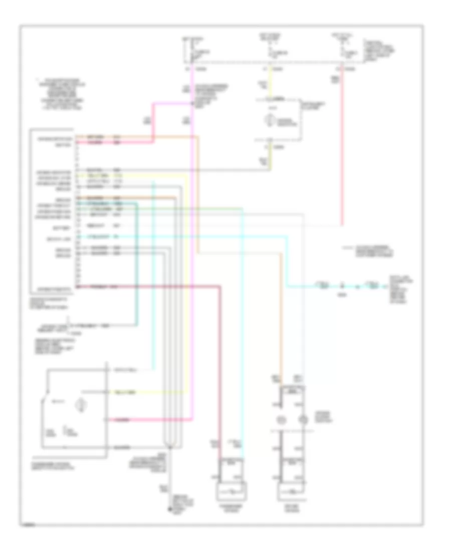
List of elements for Supplemental Restraints Wiring Diagram for Ford F550 Super Duty 2000:
- (behind bottom of right kick panel) g203
- (in main harness, near breakout to air bag diagnostic module) s203
- (in main harness, near breakout to customer access)
- Air bag diagnostic module (in center of dash)
- Air bag dr fd mon
- Air bag dr return
- Air bag indicator
- Air bag pass mon
- Air bag pass rtn
- Air bag sliding contact
- Air bag sw lp dr
- Air bag sw sense
- Air bag tone out
- Air bag tone request input
- Battery
- C240a
- C242a
- C242b
- C250a
- Central junction box (behind lower left side of dash)
- Data link connector (dlc) (partial) (behind center of dash)
- Driver air bag
- Fuse 2 10a
- Fuse 22 10a
- Fuse 29 5a
- Generic electronic module (gem) (behind lower left side of dash)
- Ground
- Hot at all times
- Hot in run
- Hot in run or start
- Ignition
- Instrument cluster
- Iso 9141 link
- Nca
- Ohms
- Passenger air bag
- Passenger air bag deactivation switch
- Pin shorting bar engaged when module connector is disconnected: (shorting bar connected between following pins: 1-15, 7-21, 8-22 & 14-28)
- S202 (in main harness, near breakout to air bag diagnostic module)
- S225
- Shorting bar
 English