SUPPLEMENTAL RESTRAINTS
Supplemental Restraints Wiring Diagram (1 of 2) for Ford Five Hundred SEL 2005

List of elements for Supplemental Restraints Wiring Diagram (1 of 2) for Ford Five Hundred SEL 2005:
- c310b 1-2 & 3-4 & 5-6 7-8 & 9-10 & 21-22
- (near driver seat)
- (near passenger seat)
- C2280b
- C2280e
- C310a
- C310b
- Can+
- Can-
- Computer data lines system
- Driver seat belt buckle sensor (near driver seat)
- Driver seat belt buckle switch (near driver seat)
- Driver seat belt tensioner
- Drivers side air bag module (in bottom left of driver seat)
- Drvr signal
- Fuse 7.5a
- G201 (bottom of left "a" pillar)
- G300 (late production freestyle) g301 (early production freestyle) (center right "c"pillar)
- G308 (five hundred/ montego) (center of right rear fender)
- Hot in start or run
- Nca
- Pad ind
- Pass signal
- Passenger air bag deactivation(pad) indicator
- Passenger seat belt buckle switch (near passenger seat)
- Passenger seat belt tensioner
- Pin shorting bars engaged when module connector is disconnected from harness (shorting bars are connected between pins: c310a 1-2 & 3-4 & 5-6 & 13-14
- Red
- Red/pnk
- Restraints control module (under center console)
- S344
- Shorting bar
- Sig rtn
- Signal
- Smart junction box (sjb) (behind left side of dash)
- Supp volt
- Vpwr
- Vref
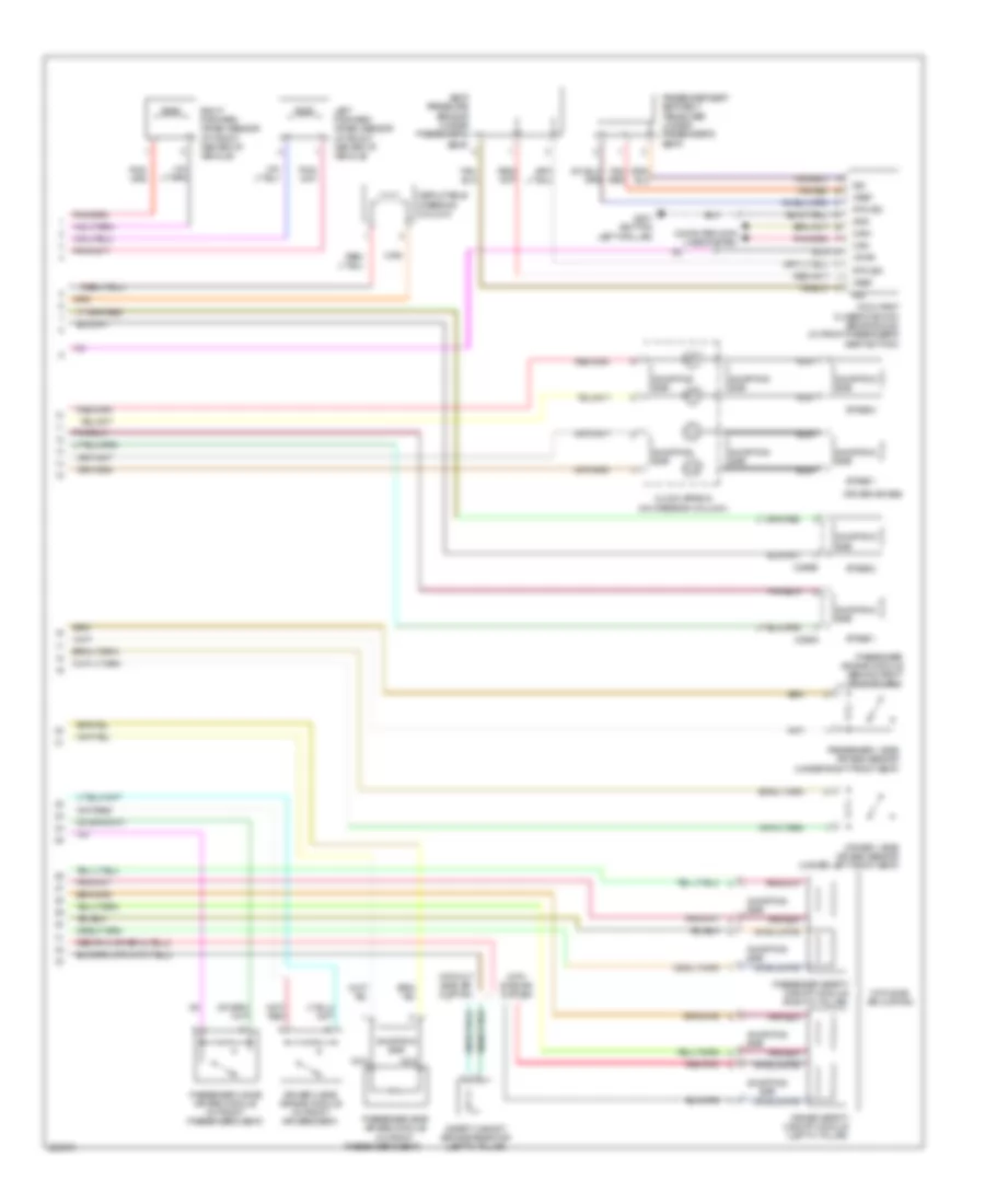
Supplemental Restraints Wiring Diagram (2 of 2) for Ford Five Hundred SEL 2005
List of elements for Supplemental Restraints Wiring Diagram (2 of 2) for Ford Five Hundred SEL 2005:
- Bar
- C256a
- C256b
- Can+
- Can-
- Clock spring (on steering column)
- Computer data lines system
- Deployable steering column
- Driver 1 side air bag sensor (under left front seat)
- Driver 2 side air bag module (in front drivers seat)
- Driver air bag
- Driver safety canopy module (left''c" pillar)
- G201 (bottom left"a"pillar)
- Gnd
- Left forward crash sensor (at front center of vehicle)
- Nca
- Occupant classificantion sensor(ocs) (in front passenger's seat bottom)
- Passenger 1 side air bag sensor (under right front seat)
- Passenger 2 side air bag module (in front passenger's seat)
- Passenger air bag module (behind right side of dash)
- Passenger safety canopy module (right''c" pillar)
- Passenger seat seat belt tensioner (under passenger's seat)
- Passenger side air bag module (in front
- Passenger's seat)
- Red/pnk
- Right forward crash sensor (at front center of vehicle)
- Rtn sig
- Safety canopy bridge resistor (left''c" pillar)
- Seat pressure sensor (under passenger's
- Seat)
- Shorting
- Shorting bar
- Sig
- Stage 1
- Stage 2
- Tan/ red
- Tan/red
- Vpwr
- Vref
- With side air curtain
- With side air curtain
- Without side air curtain