SUPPLEMENTAL RESTRAINTS
Supplemental Restraints Wiring Diagram (1 of 2) for Ford Taurus SES 2004

List of elements for Supplemental Restraints Wiring Diagram (1 of 2) for Ford Taurus SES 2004:
- (at base of left "a" pillar) g202
- (right rear side of engine compt) s227
- (right rear side of engine compt) s331
- Air bag deactivation warning
- Air bag indicator
- C2280b
- C2280c
- C310a
- C310b
- Can+
- Can-
- Data link connector (dlc) (mounted on dash, below steering column)
- Disabled ind
- Fuse 10a
- G202 (at base of left "a" pillar)
- Ground
- Hot in run or start
- Ind ctrl
- Instrument cluster
- Integrated control panel
- Iso
- Left safety belt assembly
- Left side impact sensor
- Microprosser
- Nca
- Pin shorting bars engaged when module connector is disconnected from harness. shorting bars are connected between following pins: 1-2, 3-4, 5-6, 13-14 & 16-19 c310a 3-4 & 5-6 c310b
- Red
- Restraints control module (under center of dash)
- Right safety belt assembly (under passenger seat)
- Right side impact sensor
- S209 (left side of dash, behind instrument cluster)
- S227 (right rear side of engine compt)
- S250 (left end of dash)
- Safety belt buckle pretensioner
- Safety belt buckle switch
- Shorting bar
- Sig rtn
- Smart junction box (under left side of dash)
- Tone
- Twisted pair
- Vpwr
- Vref
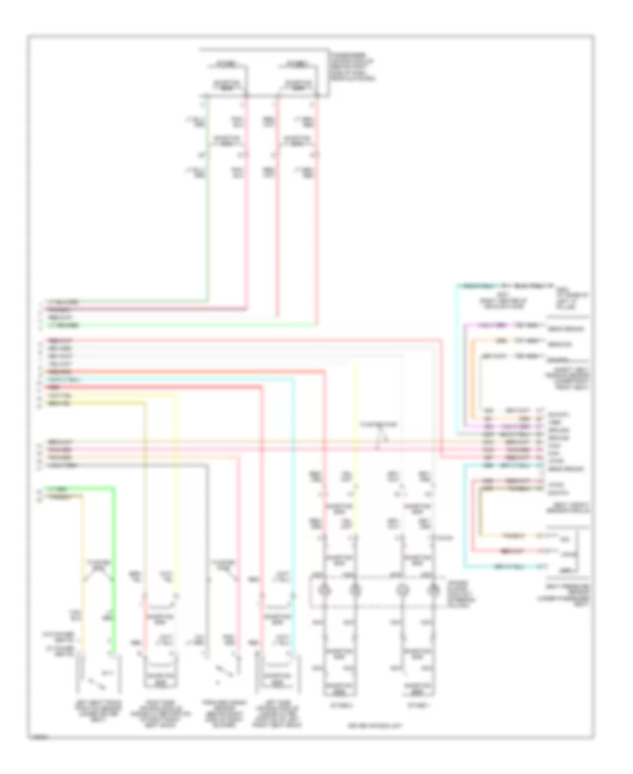
Supplemental Restraints Wiring Diagram (2 of 2) for Ford Taurus SES 2004
List of elements for Supplemental Restraints Wiring Diagram (2 of 2) for Ford Taurus SES 2004:
- (w/ power seats)
- (w/o power seats)
- Air bag sliding contact (steering column)
- C218a
- Can+
- Can-
- Driver air bag unit
- Forward crash sensor (behind right side of front bumper)
- G202 (at base of left "a" pillar)
- Gnd
- Ground
- Left seat track position sensor (under driver seat)
- Left side air bag module (inside outer portion of left front seat back)
- Nca
- Passenger's air bag module (behind right side of dash, near glove box)
- Red
- Right side air bag module (inside outer portion of right front seat back)
- S331 (right center of vehicle floor)
- Safety belt tension sensor (under right front seat)
- Seat pressure sensor (under passenger seat)
- Seat weight sensor module
- Sens ground
- Sens sig
- Shorting bar
- Sig
- Sig rtn
- Stage 1
- Stage 2
- Twisted pair
- Vpwr
- Vref