SUPPLEMENTAL RESTRAINTS
Supplemental Restraint Wiring Diagram for Oldsmobile Silhouette GLS 1997
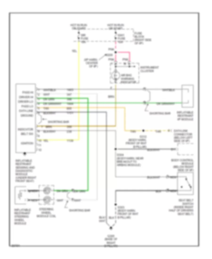
List of elements for Supplemental Restraint Wiring Diagram for Oldsmobile Silhouette GLS 1997:
- (i/p harn, center of i/p)
- A nca
- Air bag warning indicator
- Belt sw
- Body control module (below right side of i/p)
- Data line
- Data link connector (below left side of i/p)
- Driver hi
- Driver lo
- Fuse block (right side of i/p)
- G305 (base of right b pillar)
- Ground
- Hot in run or start
- Ign1 fuse 10a
- Ignition
- Indicator
- Inflatable restraint i/p module
- Inflatable restraint sensing and diagnostic module (under right front seat)
- Inflatable restraint steering wheel module
- Instrument cluster
- Nca
- Nca b
- Pass hi
- Pass lo
- Pnk
- S209
- S303 (body harn, front of rht b pillar)
- S304 (body harn, near breakout to airbag module)
- Seat belt switch (inside right half of drivers seat belt)
- Shorting bar
- Sir fuse 15a
- Steering wheel module coil
- Tan
 English