TRANSMISSION
5.4L
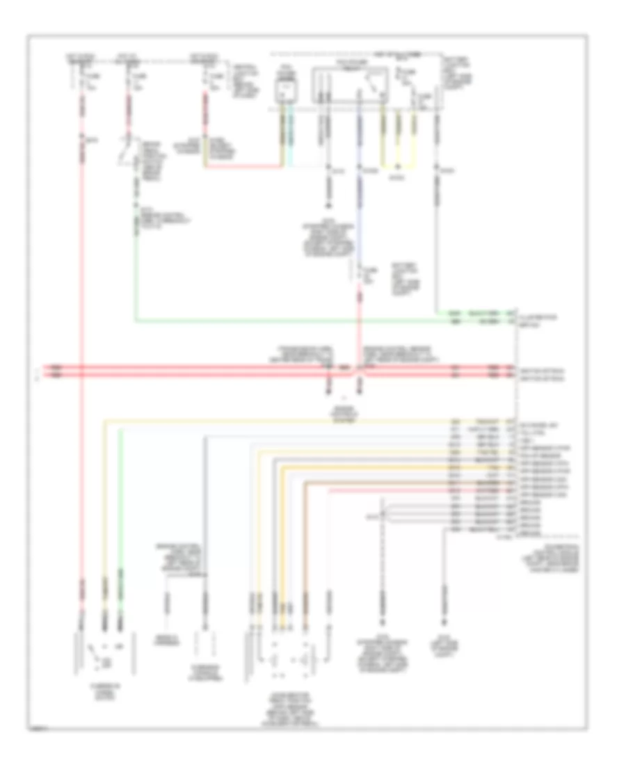
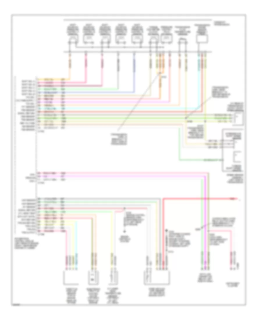
5.4L, A/T Wiring Diagram, with 4R70E/4R75E (1 of 2) for Ford E450 Super Duty 2006

List of elements for 5.4L, A/T Wiring Diagram, with 4R70E/4R75E (1 of 2) for Ford E450 Super Duty 2006:
- (at left side of transmission) digital transmission range (dtr) sensor
- (at rear of transmission) output shaft speed (oss) sensor
- (left side of transmission) turbine shaft speed (tss) sensor
- (window regulator relay switch harn, near breakout to steering column)
- 4r70e/4r75e transmission
- C175a
- C175b
- C175c
- C220a
- Can +
- Can -
- Data link connector (below left side of dash)
- Dtr tr1
- Dtr tr2
- Dtr tr3
- Dtr tr4
- Electronic pressure control solenoid
- Electronic throttle control (etc) motor (top right front of engine)
- Engine controls system
- Epc sol
- Etc return
- Etc wot cntrl
- G104 (stripped chassis: right side of engine compt) (except stripped chassis: left side of engine compt)
- Iat sensor
- Instrument cluster
- Maf sensor
- Mass air flow (maf) sensor (at center of engine compt)
- Oss sig
- Powertrain control module (left rear of engine compt, near brake master cylinder)
- Prog sig
- Red
- S136 (engine control sensor harn, near breakout to left rear of engine)
- S172
- S198 (near breakout to center rear of trans)
- S228 (main harn, near breakout to left side of dash)
- S269
- Shift sol a
- Shift sol b
- Shift solenoids
- Signal return
- Tcc sol
- Tft sensor sig
- Throttle position sensor (top of engine, near air intake)
- Torque converter clutch solenoid
- Tps 2 sig
- Tps output
- Tps sig
- Tps sig return
- Tr-p ground
- Tr1
- Tr2
- Tr3
- Tr4
- Transmission fluid temperature sensor
- Tss sensor
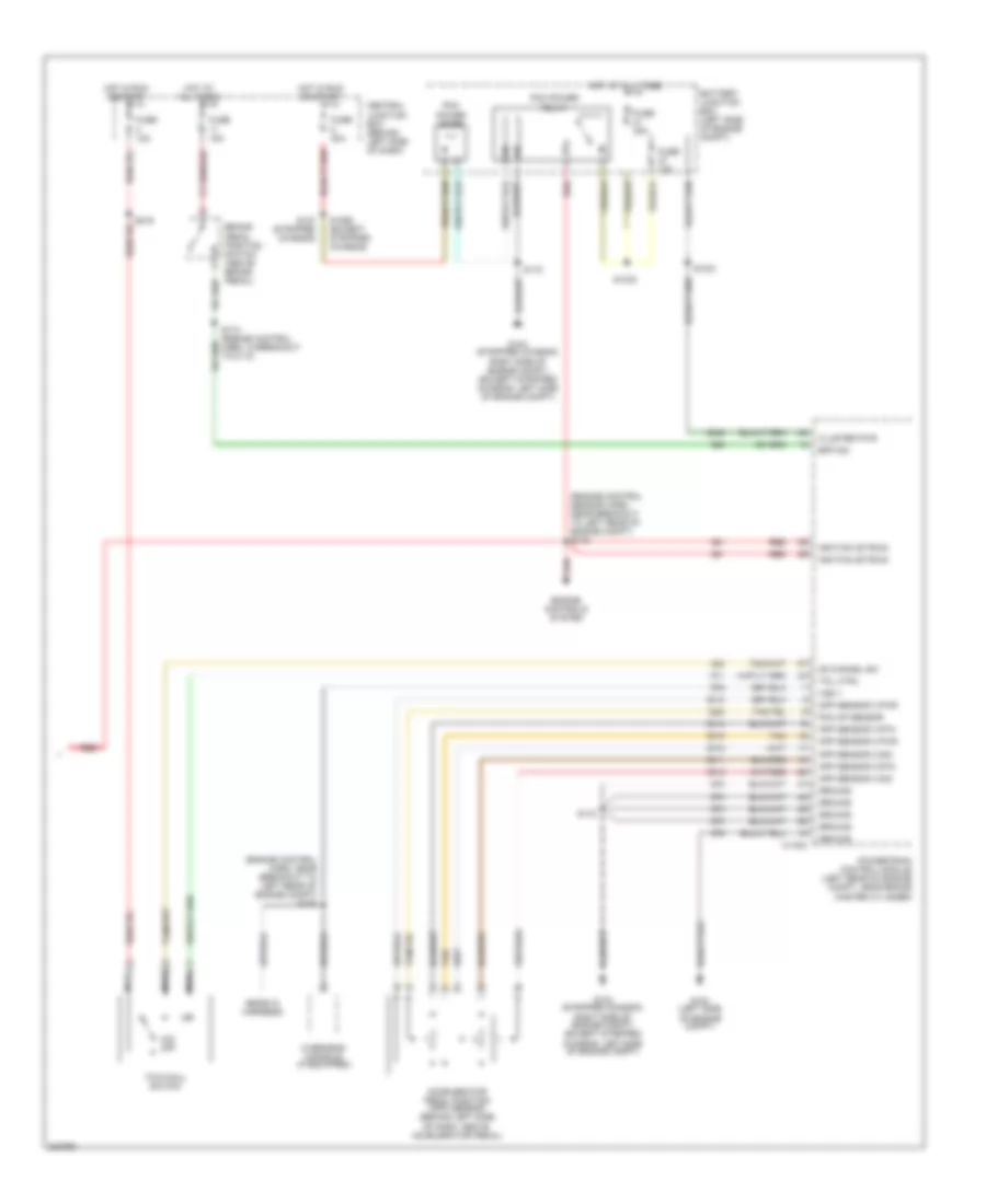
5.4L, A/T Wiring Diagram, with 4R70E/4R75E (2 of 2) for Ford E450 Super Duty 2006
List of elements for 5.4L, A/T Wiring Diagram, with 4R70E/4R75E (2 of 2) for Ford E450 Super Duty 2006:
- (ends in harness)
- (engine control harn, near breakout to left rear of engine compt) s135
- (engine control sensor harn, near breakout to left rear of engine compt) s142
- (transmission harn, near breakout to center rear of trans) s100
- Accelerator pedal position (app) sensor (behind left side of dash, above accelerator pedal)
- App sensor 2 pwr
- App sensor 2 rtn
- App sensor 2 sig
- App sensor 3 pwr
- App sensor 3 rtn
- App sensor 3 sig
- Battery junction box (left side of engine compt)
- Bpp sw
- Brake pedal position switch (above brake pedal)
- C175a
- Central junction box (behind left side of dash)
- Cluster pwr
- Engine controls system
- Fuse 10a
- Fuse 15a
- Fuse 20a
- Fuse 30a
- G100 (left side of engine compt)
- G104 (stripped chassis: right side of engine compt) (except stripped chassis: left side of engine compt)
- Ground
- Hot at all times
- Hot in run or start
- Ignition (st/run)
- Nca
- O/d off
- Od cancel sw
- Overdrive cancel switch
- Overhead console (if equipped)
- Pcm ap sensor
- Pcm power diode
- Pcm power relay
- Powertrain control module (left rear of engine compt, near brake master cylinder)
- Red
- S1021
- S1033
- S1035
- S1065 (except stripped chassis)
- S127 (stripped chassis)
- S172
- S174 (engine control harn, in breakout to c110)
- S216
- Tan
- Tcil ctrl
- Vss +
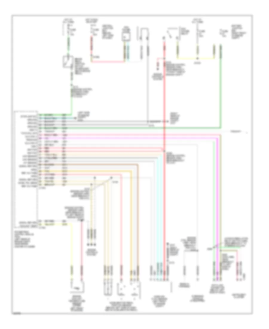
5.4L, A/T Wiring Diagram, with Torqshift (1 of 2) for Ford E450 Super Duty 2006
List of elements for 5.4L, A/T Wiring Diagram, with Torqshift (1 of 2) for Ford E450 Super Duty 2006:
- (at rear of transmission) output shaft speed sensor
- (transmission harn, in breakout to right side of transmission)
- (transmission harn, near breakout to center rear of transmission)
- (window regulator relay switch harn, near breakout to steering column)
- C175a
- C175b
- C175c
- C220a
- Can +
- Can -
- Cyl head temp
- Cylinder head temperature sensor (top front
- Data link connector (below left side of dash)
- Electronic throttle control motor (top right front of engine)
- Engine controls system
- Etc return
- Etc wot cntrl
- G104 (stripped chassis: right side of engine compt) (except stripped chassis: left side of engine compt)
- Iat sensor
- Instrument cluster
- Intermediate shaft speed sensor
- Iss sensor
- Maf sensor
- Mass air flow (maf) sensor (at center of engine compt)
- Of left cyl head)
- Oss sensor
- Powertrain control module (left rear of engine compt, near brake master cylinder)
- Pressure control (pc-a) solenoid
- Prog sig
- Red
- Ref voltage
- S1037 (transmission harn, near breakout to top center transmission)
- S123
- S136 (engine control sensor harn, near breakout to left rear of engine)
- S172
- S198
- S228 (main harn, near breakout to left side of dash)
- S269
- Shift sol a
- Shift sol b
- Shift sol c
- Shift sol d
- Shift sol e
- Shift solenoid pressure control a (sspc-a)
- Shift solenoid pressure control b (sspc-b)
- Shift solenoid pressure control c (sspc-c)
- Shift solenoid pressure control d (sspc-d)
- Shift solenoid pressure control e (sspc-e)
- Signal return
- Speed sensor assembly (left side of transmission)
- Tcc sol
- Tft sensor
- Throttle position sensor (top of engine, near air intake)
- Torqshift transmission
- Torque converter clutch solenoid
- Tps 2 sig
- Tps output
- Tps sig
- Tps sig return
- Transmission fluid temperature sensor
- Transmission range sensor assembly (tr-p)
- Trs sensor
- Tss sensor
- Turbine shaft speed sensor
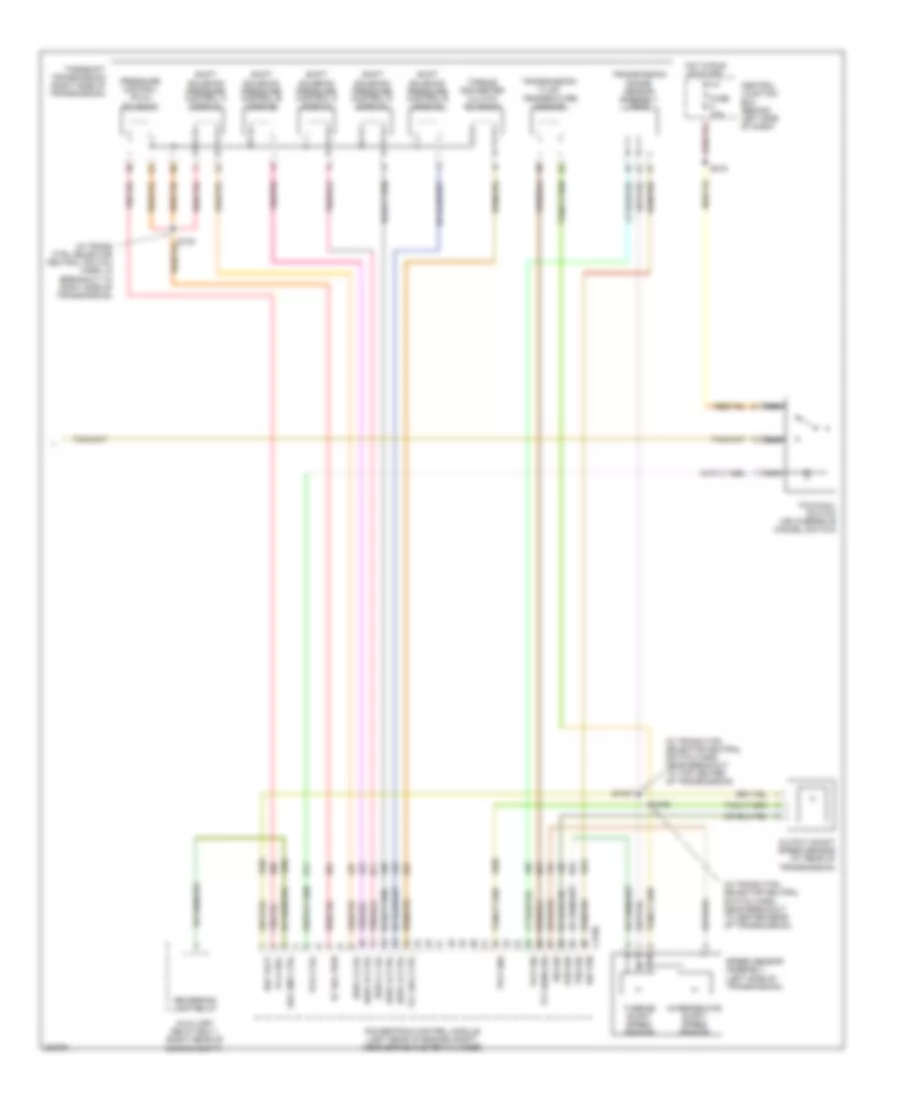
5.4L, A/T Wiring Diagram, with Torqshift (2 of 2) for Ford E450 Super Duty 2006
List of elements for 5.4L, A/T Wiring Diagram, with Torqshift (2 of 2) for Ford E450 Super Duty 2006:
- (ends in harness)
- (engine control harn, near breakout to left rear of engine compt) s135
- (engine control sensor harn, near breakout to left rear of engine compt) s142
- Accelerator pedal position (app) sensor (behind left side of dash, above accelerator pedal)
- App sensor 2 pwr
- App sensor 2 rtn
- App sensor 2 sig
- App sensor 3 pwr
- App sensor 3 rtn
- App sensor 3 sig
- Battery junction box (left side of engine compt)
- Bpp sw
- Brake pedal position switch (above brake pedal)
- C175a
- Central junction box (behind left side of dash)
- Cluster pwr
- Engine controls system
- Fuse 10a
- Fuse 15a
- Fuse 30a
- G100 (left side of engine compt)
- G104 (stripped chassis: right side of engine compt) (except stripped chassis: left side of engine compt)
- Ground
- Hot at all times
- Hot in run or start
- Ignition (st/run)
- Nca
- O/d off
- Od cancel sw
- Overhead console (if equipped)
- Pcm ap sensor
- Pcm power diode
- Pcm power relay
- Powertrain control module (left rear of engine compt, near brake master cylinder)
- Red
- S1021
- S1033
- S1065 (except stripped chassis)
- S127 (stripped chassis)
- S172
- S174 (engine control harn, in breakout to c110)
- S216
- Tan
- Tcil ctrl
- Tow/haul switch
- Vss +
6.0L DIESEL
6.0L Diesel, A/T Wiring Diagram (1 of 2) for Ford E450 Super Duty 2006
List of elements for 6.0L Diesel, A/T Wiring Diagram (1 of 2) for Ford E450 Super Duty 2006:
- (ends in harness)
- (engine control sensor harn, near breakout to left rear of engine compt) s1059
- (engine control sensor harn, near breakout to right side of engine compt)
- (engine ctrl sensor harn, near breakout for c131) s135
- (left side of engine compt) g100
- (right rear of engine compt) g107
- (window regulator relay switch harn, near breakout to steering column)
- Accel pdl sens
- Accelerator pedal position sensor (behind left side of dash, above accelerator pedal)
- Aps2
- Aps3
- Battery junction box (right front of engine compt)
- Brake pedal position switch (on bracket, above brake pedal)
- C176a
- C176c
- C220a
- Central junction box (behind left side of dash)
- Coolant temp
- Data link connector (below left side of dash)
- Dlc can h
- Dlc can l
- Engine controls system
- Engine coolant temperature sensor (upper
- Fuse 10a
- Fuse 15a
- Fuse 30a
- G107 (right rear of engine compt)
- Ground
- Hot at all times
- Hot in run or start
- Iat sensor
- Ignition
- Instrument cluster
- Left front of engine)
- Maf sensor
- Mass air- flow sensor (left front of engine compt)
- Overhead console (if equipped)
- Pcm power diode
- Pcm power relay
- Powertrain control module (pcm) (left rear of engine compt, near brake master cylinder)
- Prog sig
- Red
- Ref voltage
- S1033
- S1065
- S1068 (engine control sensor harn, near breakout to c127)
- S136
- S138 (engine control sensor harn, near breakout for c131)
- S142 red
- S172
- S228 (main harn, near breakout to left side of dash)
- S269
- Sensor harn, in breakout to c219)
- Signal return
- Stoplamp sw
- Tan
- Tow/haul sw
- Vbatt
- Vss+
6.0L Diesel, A/T Wiring Diagram (2 of 2) for Ford E450 Super Duty 2006
List of elements for 6.0L Diesel, A/T Wiring Diagram (2 of 2) for Ford E450 Super Duty 2006:
- (in trans ctrl selector neutral switch harn, in breakout to right side of transmission)
- (in trans ctrl selector neutral switch harn, near breakout to center rear of transmission)
- (in trans ctrl selector neutral switch harn, near breakout to top center of transmission)
- Auxiliary relay box 1 (right rear of engine compt)
- C176b
- Central junction box (behind left side of dash)
- Fuse 10a
- Hot in run or start
- Intermediate shaft speed sensor
- Iss sig
- Nca
- Oss sig
- Output shaft speed sensor (at rear of transmission)
- Pc sol pwr
- Pc-a sol
- Powertrain control module (left rear of engine compt, near brake master cylinder)
- Pressure control (pc-a) solenoid
- Ref volt
- Rev lmp ctrl
- Reversing lamp relay
- S1037
- S123
- S198
- S216
- Shift solenoid pressure control a (sspc-a)
- Shift solenoid pressure control b (sspc-b)
- Shift solenoid pressure control c (sspc-c)
- Shift solenoid pressure control d (sspc-d)
- Shift solenoid pressure control e (sspc-e)
- Sig trn
- Speed sensor assembly (left side of transmission)
- Sspc-a crl
- Sspc-b ctrl
- Sspc-c crl
- Sspc-d ctrl
- Sspc-e ctrl
- Tcc sol ctrl
- Tcil ctrl
- Tft sens sig
- Torqshift transmission (right side of transmission)
- Torque converter clutch solenoid
- Tow/haul switch (or overdrive cancel switch)
- Tr-p gnd
- Tr-p sig
- Transmission fluid temperature sensor
- Transmission range sensor assembly (tr-p)
- Tss sig
- Turbine shaft speed sensor
6.8L
6.8L, A/T Wiring Diagram, with Torqshift (1 of 2) for Ford E450 Super Duty 2006
List of elements for 6.8L, A/T Wiring Diagram, with Torqshift (1 of 2) for Ford E450 Super Duty 2006:
- (at rear of transmission) output shaft speed sensor
- (transmission harn, in breakout to right side of transmission)
- (transmission harn, near breakout to center rear of transmission)
- (window regulator relay switch harn, near breakout to steering column)
- C175a
- C175b
- C175c
- C220a
- Can +
- Can -
- Cyl head temp
- Cylinder head temperature sensor (top front
- Data link connector (below left side of dash)
- Electronic throttle control motor (top right front of engine)
- Engine controls system
- Etc return
- Etc wot cntrl
- G104 (stripped chassis: right side of engine compt) (except stripped chassis: left side of engine compt)
- Iat sensor
- Instrument cluster
- Intermediate shaft speed sensor
- Iss sensor
- Maf sensor
- Mass air flow (maf) sensor (at center of engine compt)
- Of left cyl head)
- Oss sensor
- Powertrain control module (left rear of engine compt, near brake master cylinder)
- Pressure control (pc-a) solenoid
- Prog sig
- Red
- Ref voltage
- S1037 (transmission harn, near breakout to top center transmission)
- S123
- S136 (engine control sensor harn, near breakout to left rear of engine)
- S172
- S198
- S228 (main harn, near breakout to left side of dash)
- S269
- Shift sol a
- Shift sol b
- Shift sol c
- Shift sol d
- Shift sol e
- Shift solenoid pressure control a (sspc-a)
- Shift solenoid pressure control b (sspc-b)
- Shift solenoid pressure control c (sspc-c)
- Shift solenoid pressure control d (sspc-d)
- Shift solenoid pressure control e (sspc-e)
- Signal return
- Speed sensor assembly (left side of transmission)
- Tcc sol
- Tft sensor
- Throttle position sensor (top of engine, near air intake)
- Torqshift transmission
- Torque converter clutch solenoid
- Tps 2 sig
- Tps output
- Tps sig
- Tps sig return
- Transmission fluid temperature sensor
- Transmission range sensor assembly (tr-p)
- Trs sensor
- Tss sensor
- Turbine shaft speed sensor
6.8L, A/T Wiring Diagram, with Torqshift (2 of 2) for Ford E450 Super Duty 2006
List of elements for 6.8L, A/T Wiring Diagram, with Torqshift (2 of 2) for Ford E450 Super Duty 2006:
- (ends in harness)
- (engine control harn, near breakout to left rear of engine compt) s135
- (engine control sensor harn, near breakout to left rear of engine compt) s142
- Accelerator pedal position (app) sensor (behind left side of dash, above accelerator pedal)
- App sensor 2 pwr
- App sensor 2 rtn
- App sensor 2 sig
- App sensor 3 pwr
- App sensor 3 rtn
- App sensor 3 sig
- Battery junction box (left side of engine compt)
- Bpp sw
- Brake pedal position switch (above brake pedal)
- C175a
- Central junction box (behind left side of dash)
- Cluster pwr
- Engine controls system
- Fuse 10a
- Fuse 15a
- Fuse 30a
- G100 (left side of engine compt)
- G104 (stripped chassis: right side of engine compt) (except stripped chassis: left side of engine compt)
- Ground
- Hot at all times
- Hot in run or start
- Ignition (st/run)
- Nca
- O/d off
- Od cancel sw
- Overhead console (if equipped)
- Pcm ap sensor
- Pcm power diode
- Pcm power relay
- Powertrain control module (left rear of engine compt, near brake master cylinder)
- Red
- S1021
- S1033
- S1065 (except stripped chassis)
- S127 (stripped chassis)
- S172
- S174 (engine control harn, in breakout to c110)
- S216
- Tan
- Tcil ctrl
- Tow/haul switch
- Vss +