TRANSMISSION
4WD Wiring Diagram for Ford Explorer Sport Trac 2005

List of elements for 4WD Wiring Diagram for Ford Explorer Sport Trac 2005:
- (at center of automatic transmission) digital transmission range (dtr) sensor
- (in engine control sensor & fuel charge wiring harness, near breakout at rear center of engine compt) s145
- (main harness, near breakout to c215) s213
- (main wiring harness, near breakout behind driver side of dash) s227
- 4wd hi
- 4wd hi ind
- 4wd lo
- 4wd lo ind
- 4wd switch
- Battery junction box (bjb) (left side of engine compt, at fender apron)
- Behind center of dash)
- Bpp switch
- Brake pedal position switch (above brake pedal)
- Breakout to c215)
- C220a
- C220b
- C274a
- C281a
- C281b
- Central junction box (cjb) (behind left side of dash)
- Central security module (behind top right side of dash)
- Computer data lines system
- Data link connector (dtc) (behind left side of dash)
- Door ajar
- Four-wheel drive control module (at right kick panel)
- Four-wheel drive switch
- Fuse 15a
- Fuse 20a
- Fuse 7.5a
- G100 (at center rear of engine compt)
- G201 (at right kick panel)
- G300 (at left kick panel)
- Ground
- Hot at all times
- Hot in run
- Hot in run or start
- Ign (run)
- Ign (st/run)
- Illum
- Instrument cluster
- Interior lights system
- Iso bus
- Microprocessor
- Motor 1
- Motor 2
- Motor 3
- Motor 4
- Motor 5
- N tow sw
- Nca
- Neutral sens
- Neutral tow indicator
- Off
- Powertrain control module (pcm) (mounted through firewall)
- S208 (in main wiring harness, near breakout behind center of dash)
- S216 (main wiring harness, near breakout behind instrument cluster)
- S220 (main wiring harness, near breakout behind center of dash)
- Sig return
- Transfer case
- Transfer case assembly
- Vss input
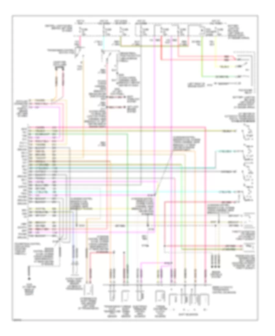
A/T Wiring Diagram for Ford Explorer Sport Trac 2005
List of elements for A/T Wiring Diagram for Ford Explorer Sport Trac 2005:
- (at center of automatic transmission) digital transmission range (dtr) sensor
- (dlc) (partial) (behind left side of dash)
- (engine control sensor & fuel charge wiring harness, near breakout at rear center of engine)
- (in engine control sensor & fuel charge wiring harness, near breakout at left center side of engine)
- (in engine control sensor & fuel charge wiring harness, near breakout at rear center of engine compartment)
- (in engine control sensor & fuel charge wiring harness, near breakout at rear center of engine)
- (in engine control sensor & fuel charge wiring harness, near breakout to c110)
- (in engine control sensor & fuel charge wiring harness, near breakout to g100)
- (in main wiring harness, near breakout behind driver side of dash) s227
- (left front of engine compt)
- 5r55e automatic transmission control solenoids
- Anti-lock brakes system
- Battery junction box (bjb) (left side of engine compt, at fender apron)
- Bpp
- Brake pedal position switch (above brake pedal)
- Central junction box (behind left side of dash)
- Computer data lines system
- Data link connector
- Dlc
- Dlc (+)
- Dlc (-)
- Ect
- Electronic pressure control (epc) solenoid
- Engine controls system
- Engine coolant temperature (ect) sensor (mounted on front of engine, left of throttle body)
- Epc
- Fuse 10a
- Fuse 15a
- Fuse 30a
- Fuse 7.5a
- G104
- G109 (at center rear of engine compt)
- G300 (at left kick panel)
- Ground
- Hot at all times
- Hot in run
- Hot in run or start
- Intermediate shaft speed (iss) sensor (left side of transmission)
- Iss
- Kapwr
- Oss
- Output shaft speed (oss) sensor (on rear of transmission)
- Pcm power diode
- Pcm power relay
- Power
- Powertrain control module (pcm) (mounted through firewall)
- R p
- Red
- S117 (in dash panel to headlamp junction wiring harness, near breakout at left center side of engine compt)
- S137
- S138
- S139
- S140
- S143
- S146
- S148
- S206 (in main wiring harness, near breakout behind center of dash)
- Shift interlock system
- Shift solenoids
- Sig rtn
- Ss a
- Ss b
- Ss c
- Ss d
- Tcc
- Tcs
- Tft
- Throttle position (tp) sensor (attached to throttle body)
- Torque converter clutch (tcc) solenoid
- Tr1
- Tr2
- Tr3a
- Tr4
- Transmission control switch (tcs)
- Transmission fluid temperature (tft) sensor
- Tss
- Turbine shaft speed (tss) sensor
- Vref