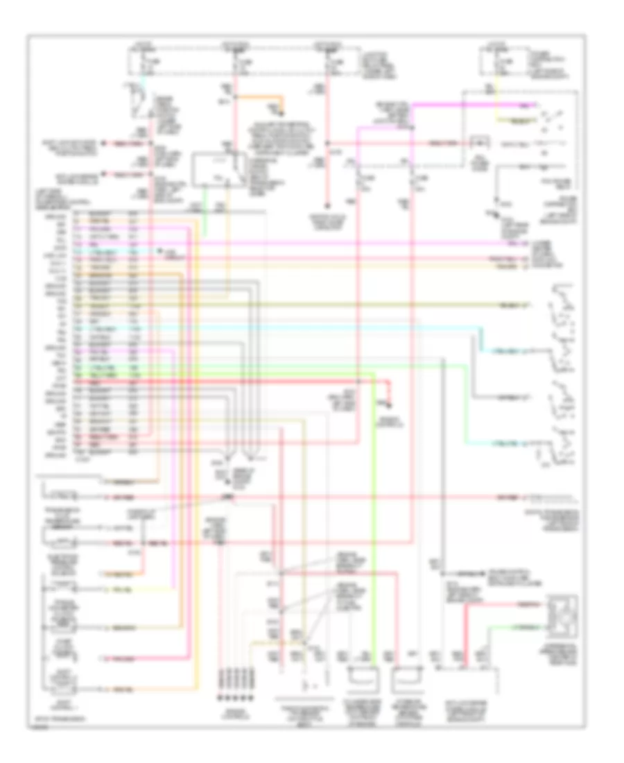
TRANSMISSION
4WD Wiring Diagram for Ford F550 Super Duty 1999

List of elements for 4WD Wiring Diagram for Ford F550 Super Duty 1999:
- 1.1k ohms
- 3.9k ohms
- 4 wheel drive mode switch
- 4x2 sol
- 4x4 high ind
- 4x4 high range indicator
- 4x4 low ind
- 4x4 low range indicator
- 4x4 mode sw
- 4x4 sol
- Anti-lock brake system module (left front of engine compt)
- Auxiliary powertrain control module, clutch pedal position switch, idle validation switch, overhead trip computer, overdrive cancel switch
- Bpp sw input
- Brake pedal position switch (under left side of dash)
- C1040
- C239
- C247
- C250
- C253
- C284
- C285
- Clutch pedal position switch, shift lock actuator, powertrain control module, anti-lock brake module
- Digital transmission range (dtr) sensor (left side of transmission)
- Fuse 10a
- Fuse 20a
- Fuse 30a
- G104 (left rear of engine compt)
- G200 (left kick panel)
- Generic electronic module (gem) (behind left side of dash)
- H2l rly ctrl
- High to low
- Hot at all times
- Hot in run
- Hot in run or start
- Ignition
- Illumination
- Instrument cluster
- Interior lights (instrument illumination)
- Junction box fuse/ relay panel (under left side of dash)
- L2h rly ctrl
- Low to high
- Neutral sw in
- Ohms
- Power distribution box (left side of engine compt)
- Red
- S124
- S205
- S206
- S213
- S250
- S251
- S255
- Shift lock actuator, drl relay
- Shift motor
- Sw a input
- Sw b input
- Sw c input
- Sw d input
- Tod rly ctrl
- Torque on demand relay
- Transfer case assembly (below vehicle, behind transmission)
- Transfer case shift relay module (in engine compt, next to central junction box)
- Vacuum hublock solenoid (right side of engine compt)
- Vacuum pump, speed control module, back-up lamp switch
6.8L
6.8L, A/T Wiring Diagram for Ford F550 Super Duty 1999
List of elements for 6.8L, A/T Wiring Diagram for Ford F550 Super Duty 1999:
- (engine ctrl harn, near battery junction box) s120
- (engine harn, left side of dash) s122
- (engine harn, near breakout to fuel injector)
- (engine harn, near breakout to pcm)
- (in back-up lamp harn)
- (left side of firewall) powertrain control module (pcm)
- (rear of engine compt) g123
- (under
- 4r100 transmission
- 4wd circuit
- 4wd low
- Anti-lock brake system module
- Anti-lock brake system module (left front of engine compt)
- Auxiliary powertrain control module, clutch pedal position switch, idle validation switch, overhead trip computer, instrument cluster
- Boo
- Brake pedal position switch (under left side of dash)
- C1027
- Ccs
- Center of dash) data link connector
- Cht
- Coast clutch control
- Cruise control, body computer, instrument cluster
- Cylinder head temperature (cht) sensor (top front of engine)
- Data
- Differential speed sensor (center of rear axle)
- Digital transmission range sensor (left side of transmission)
- Dlc (+)
- Dlc (-)
- Electronic pressure control solenoid
- Engine controls
- Epc
- Fuse 10a
- Fuse 20a
- Fuse 30a
- Fuse 5a
- G104 (left rear of engine compt)
- Ground
- Hot at all times
- Hot in run or start
- Iat
- Ignition coils, radio noise capacitor
- Intake air temperature sensor (on intake manifold)
- Junction box fuse/ relay panel (under left side of dash)
- Of dash)
- Overdrive cancel switch (end of transmission selector lever)
- Pcm power diode
- Pcm power relay
- Power distribution box (left side of engine compt)
- R p
- Red
- Red/ pnk
- Red/pnk
- S102
- S106
- S114
- S115 (engine harn, left side of engine compt)
- S123 (eng harn, left side of dash)
- S132
- S133
- S138
- S139
- S179
- S213
- Shift control 1
- Shift control 2
- Shift lock actuator, gem, clutch pedal position switch
- Side of eng compt)
- Sig rtn
- Ss1
- Ss2
- Tcc
- Tcil
- Tcs
- Tft
- Throttle position (tp) sensor (on throttle body)
- Torque converter clutch solenoid
- Tr1
- Tr2
- Tr3
- Tr4
- Transmission fluid temperature sensor
- Vpwr
- Vref
- Vss in
7.3L DIESEL
7.3L Diesel, A/T Wiring Diagram for Ford F550 Super Duty 1999
List of elements for 7.3L Diesel, A/T Wiring Diagram for Ford F550 Super Duty 1999:
- (engine harn, left side of dash)
- (engine harn, left side of engine compt)
- (in backup lamp harn) s139
- (left side of firewall) powertrain control module (pcm)
- (main harn, center of dash)
- (rear of engine compt) g123
- (under
- 4r100 transmission
- 4wd circuit
- 4wd low
- Accelerator position sensor (under left side of dash)
- Anti-lock brake system module
- Anti-lock brake system module (left front of engine compt)
- Aps
- Auxiliary powertrain control module
- Auxiliary powertrain control module, clutch pedal position switch, idle validation switch, overhead trip computer, instrument cluster
- Boo
- Brake pedal position switch (under left side of dash)
- C1027
- Ccs
- Center of dash) data link connector
- Coast clutch control
- Cruise control, body computer, instrument cluster
- Data
- Differential speed sensor (center of rear axle)
- Digital transmission range sensor (left side of transmission)
- Dlc (+)
- Dlc (-)
- Electronic pressure control solenoid
- Engine controls
- Epc
- Fuel heater, wastegate solenoid control
- Fuse 10a
- Fuse 30a
- Fuse 5a
- G104 (left rear of engine compt)
- Ground
- Hot at all times
- Hot in run or start
- Iat
- Intake air temperature sensor (on intake manifold)
- Junction box fuse/ relay panel (under left side of dash)
- Of dash)
- Oss
- Output shaft speed sensor (top of transmission)
- Overdrive cancel switch (end of transmission selector lever)
- Pcm power diode
- Pcm power relay
- Power distribution box (left side of engine compt)
- R p
- Red
- Red/ pnk
- Red/pnk
- S102
- S106
- S114
- S115 (engine harn, left side of dash)
- S123
- S138 (in back-up lamp harn)
- S179
- S213
- S219
- S221
- Shift control 1
- Shift control 2
- Shift lock actuator, gem, clutch pedal position switch
- Side dash) s222
- Side of eng compt)
- Sig rtn
- Ss1
- Ss2
- Tcc
- Tcil
- Tcs
- Tft
- Torque converter clutch solenoid
- Tr1
- Tr2
- Tr3
- Tr4
- Transmission fluid temperature sensor
- Tss
- Turbine shaft speed sensor (top of transmission)
- Vpwr
- Vref
- Vss in