TRANSMISSION
4.2L
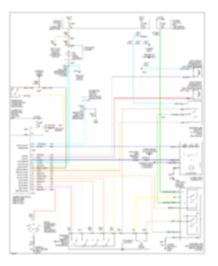
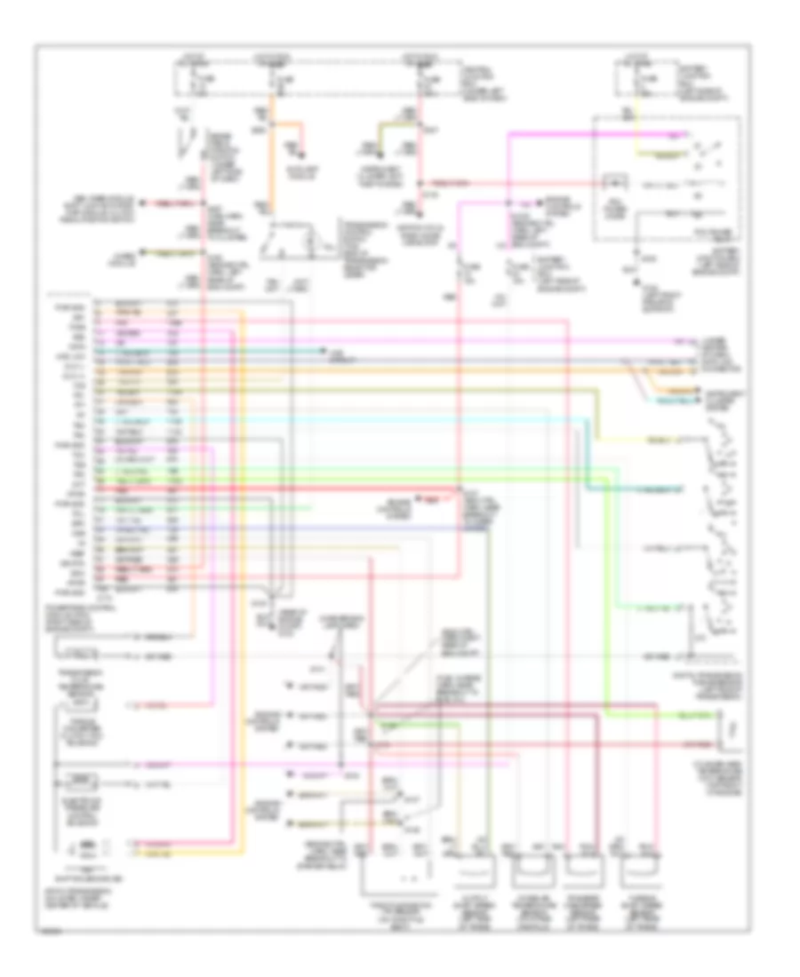
4.2L, A/T Wiring Diagram, 4R70W for Ford Pickup F250 Super Duty 1999

List of elements for 4.2L, A/T Wiring Diagram, 4R70W for Ford Pickup F250 Super Duty 1999:
- (engine ctrl harn, near breakout to starter relay)
- (engine ctrl harn, right rear of engine compt)
- (fuel charge harn, near breakout to fuel inj)
- (in reversing lamp harn)
- (rear of engine compartment) g123
- (under center of dash) data link connector
- 4r70w transmission (mounted under center of vehicle)
- 4wabs module
- 4wd circuit
- 4wd low
- Autolamp module
- Battery junction box (left side of engine compt)
- Boo
- Brake pedal position switch (under left side of dash)
- C174
- Central junction box (under left side of dash)
- Cht
- Cylinder head temperature (cht) sensor (4.2l: left side of engine) (4.6l: top front of engine)
- Data
- Digital transmission range sensor (left side of transmission)
- Dlc (+)
- Dlc (-)
- Electronic pressure control solenoid
- Engine controls system
- Epc
- Fuse 15a
- Fuse 30a
- Fuse 5a
- G108 (left front radiator support)
- Gem, rabs module, shift lock actuator, rap module, clutch pedal position switch
- Hot at all times
- Hot in run or start
- Iat
- Ignition coils, radio noise capacitor
- Instrument cluster system
- Instrument cluster, anti- theft system
- Intake air temperature sensor (on intake manifold)
- Oss
- Output shaft speed sensor (left side of trans)
- Pcm power diode
- Pcm power relay
- Pnk
- Powertrain control module (pcm) (right side of engine compt)
- Pwr gnd
- R p
- Red
- S100
- S106
- S116
- S127 (eng ctrl harn, near breakout to wiper motor)
- S135
- S136
- S137
- S138
- S140
- S141
- S160 (engine ctrl harn, left rear of eng compt)
- S225
- S237
- S297 (main harn, near breakout to cluster)
- Shift solenoids (ss)
- Sig rtn
- Ss1
- Ss2
- Tcc
- Tcil
- Tcs
- Tcss
- Tft
- Throttle position (tp) sensor (on throttle body)
- Torque converter clutch (tcc) solenoid
- Tr1
- Tr2
- Tr3
- Tr4
- Transfer case speed sensor (left rear of trans)
- Transmission control switch (tcs) (end of transmission selector lever)
- Transmission fluid temperature sensor
- Vpwr
- Vref
4WD Wiring Diagram, Electronic for Ford Pickup F250 Super Duty 1999
List of elements for 4WD Wiring Diagram, Electronic for Ford Pickup F250 Super Duty 1999:
- (lower right kick panel) g203
- (main harn, near breakout to gem)
- (right side of engine compt) 4x2 center axle disconnect solenoid
- (right side of engine compt) 4x4 center axle disconnect solenoid
- (under left side of dash) central junction box
- 1.1k ohms
- 3.9k ohms
- 4 wheel drive mode switch
- 4wd low out
- 4wd output
- 4x2 sol
- 4x4 high ind
- 4x4 high range indicator
- 4x4 mode sw
- 4x4 sol
- Anti-lock brake module
- Anti-lock brakes
- Apron) g105
- Batt
- Battery junction box (left side of engine compt)
- Bpp sw input
- Brake pedal position switch (under left side of dash)
- C174
- C236
- C239
- C241
- C243
- Central junction box (under left side of dash)
- Digital transmission range (dtr) sensor (left side of transmission)
- Exterior lights system
- Flasher relay
- Fuse 10a
- Fuse 30a
- Fuse 5a
- G108 (top front radiator support)
- Generic electronic module (gem) (behind left side of dash)
- H2l
- H2l rly ctrl
- Hot at all times
- Hot in run
- Illumination
- Instrument cluster
- Interior lights (instrument illumination)
- L2h
- L2h rly ctrl
- Magnetic clutch
- Neutral sw in
- Not used
- Ohms
- Powertrain control module (right side of engine compt)
- Red
- S102
- S120
- S142 (engine ctrl harn, near breakout to pwr dist box)
- S201
- S202
- S213
- S228
- S232 (main harn, near breakout to instrument cluster)
- S238
- S265
- S297
- Shift lock actuator, rear air suspension module
- Shift motor
- Sig return
- Sw a input
- Sw b input
- Sw c input
- Sw d input
- Tcec rly ctrl
- Trailer tow battery relay
- Transfer case assembly (below vehicle, behind transmission)
- Transfer case electric clutch relay (in rpo relay block)
- Transfer case shift relay module (behind center of dash)
- Wiper/washer (multi-function switch)
4WD Wiring Diagram, Mechanical for Ford Pickup F250 Super Duty 1999
List of elements for 4WD Wiring Diagram, Mechanical for Ford Pickup F250 Super Duty 1999:
- (engine ctrl harn, near breakout to pwr dist box) s142
- (main harn, near breakout to instrument cluster)
- (right side of engine compt) 4x2 center axle disconnect solenoid
- (right side of engine compt) 4x4 center axle disconnect solenoid
- 4x2
- 4x2 sol
- 4x4 high ind
- 4x4 high range indicator
- 4x4 low & high indicator switch (left side of transmission)
- 4x4 sol
- 4x4 sw in
- Anti-lock brake module
- Battery junction box (left side of engine compt)
- C174
- C236
- C241
- Central junction box (under left side of dash)
- Flasher relay
- Fuse 10a
- Fuse 30a
- Fuse 5a
- Generic electronic module (gem) (behind left side of dash)
- Hot at all times
- Hot in run
- Instrument cluster
- Magnetic clutch
- Not used
- Powertrain control module (right side of engine compt)
- Red
- S120
- S228
- S232
- S265
- Shift lock actuator, rear air suspension module
- Shift on the fly relay (in rpo relay block)
- Sotf rly ctrl
- Trailer tow battery relay
- Transfer case assembly
4.6L
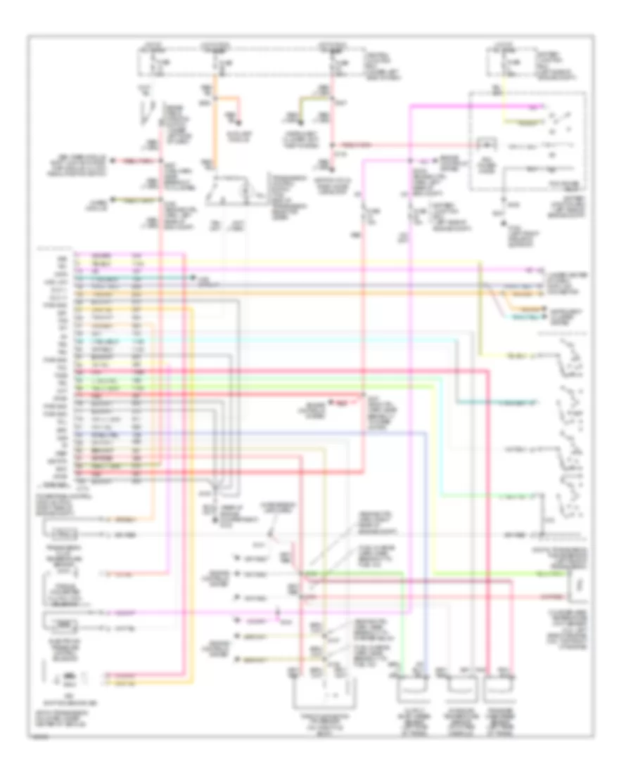
4.6L, A/T Wiring Diagram, 4R70W for Ford Pickup F250 Super Duty 1999
List of elements for 4.6L, A/T Wiring Diagram, 4R70W for Ford Pickup F250 Super Duty 1999:
- (engine ctrl harn, near breakout to starter relay)
- (engine ctrl harn, right rear of engine compt)
- (fuel charge harn, near breakout to fuel inj)
- (in reversing lamp harn)
- (rear of engine compartment) g123
- (under center of dash) data link connector
- 4r70w transmission (mounted under center of vehicle)
- 4wabs module
- 4wd circuit
- 4wd low
- Autolamp module
- Battery junction box (left side of engine compt)
- Boo
- Brake pedal position switch (under left side of dash)
- C174
- Central junction box (under left side of dash)
- Cht
- Cylinder head temperature (cht) sensor (4.2l: left side of engine) (4.6l: top front of engine)
- Data
- Digital transmission range sensor (left side of transmission)
- Dlc (+)
- Dlc (-)
- Electronic pressure control solenoid
- Engine controls system
- Epc
- Fuse 15a
- Fuse 30a
- Fuse 5a
- G108 (left front radiator support)
- Gem, rabs module, shift lock actuator, rap module, clutch pedal position switch
- Hot at all times
- Hot in run or start
- Iat
- Ignition coils, radio noise capacitor
- Instrument cluster system
- Instrument cluster, anti- theft system
- Intake air temperature sensor (on intake manifold)
- Oss
- Output shaft speed sensor (left side of trans)
- Pcm power diode
- Pcm power relay
- Pnk
- Powertrain control module (pcm) (right side of engine compt)
- Pwr gnd
- R p
- Red
- S100
- S106
- S116
- S127 (eng ctrl harn, near breakout to wiper motor)
- S135
- S136
- S137
- S138
- S140
- S141
- S160 (engine ctrl harn, left rear of eng compt)
- S225
- S237
- S297 (main harn, near breakout to cluster)
- Shift solenoids (ss)
- Sig rtn
- Ss1
- Ss2
- Tcc
- Tcil
- Tcs
- Tcss
- Tft
- Throttle position (tp) sensor (on throttle body)
- Torque converter clutch (tcc) solenoid
- Tr1
- Tr2
- Tr3
- Tr4
- Transfer case speed sensor (left rear of trans)
- Transmission control switch (tcs) (end of transmission selector lever)
- Transmission fluid temperature sensor
- Vpwr
- Vref
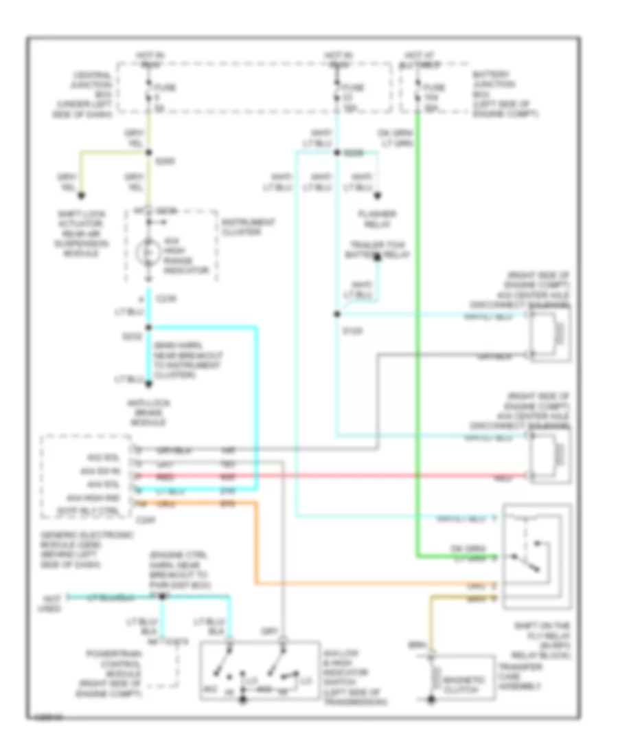
4WD Wiring Diagram, Electronic for Ford Pickup F250 Super Duty 1999
List of elements for 4WD Wiring Diagram, Electronic for Ford Pickup F250 Super Duty 1999:
- (lower right kick panel) g203
- (main harn, near breakout to gem)
- (right side of engine compt) 4x2 center axle disconnect solenoid
- (right side of engine compt) 4x4 center axle disconnect solenoid
- (under left side of dash) central junction box
- 1.1k ohms
- 3.9k ohms
- 4 wheel drive mode switch
- 4wd low out
- 4wd output
- 4x2 sol
- 4x4 high ind
- 4x4 high range indicator
- 4x4 mode sw
- 4x4 sol
- Anti-lock brake module
- Anti-lock brakes
- Apron) g105
- Batt
- Battery junction box (left side of engine compt)
- Bpp sw input
- Brake pedal position switch (under left side of dash)
- C174
- C236
- C239
- C241
- C243
- Central junction box (under left side of dash)
- Digital transmission range (dtr) sensor (left side of transmission)
- Exterior lights system
- Flasher relay
- Fuse 10a
- Fuse 30a
- Fuse 5a
- G108 (top front radiator support)
- Generic electronic module (gem) (behind left side of dash)
- H2l
- H2l rly ctrl
- Hot at all times
- Hot in run
- Illumination
- Instrument cluster
- Interior lights (instrument illumination)
- L2h
- L2h rly ctrl
- Magnetic clutch
- Neutral sw in
- Not used
- Ohms
- Powertrain control module (right side of engine compt)
- Red
- S102
- S120
- S142 (engine ctrl harn, near breakout to pwr dist box)
- S201
- S202
- S213
- S228
- S232 (main harn, near breakout to instrument cluster)
- S238
- S265
- S297
- Shift lock actuator, rear air suspension module
- Shift motor
- Sig return
- Sw a input
- Sw b input
- Sw c input
- Sw d input
- Tcec rly ctrl
- Trailer tow battery relay
- Transfer case assembly (below vehicle, behind transmission)
- Transfer case electric clutch relay (in rpo relay block)
- Transfer case shift relay module (behind center of dash)
- Wiper/washer (multi-function switch)
4WD Wiring Diagram, Mechanical for Ford Pickup F250 Super Duty 1999
List of elements for 4WD Wiring Diagram, Mechanical for Ford Pickup F250 Super Duty 1999:
- (engine ctrl harn, near breakout to pwr dist box) s142
- (main harn, near breakout to instrument cluster)
- (right side of engine compt) 4x2 center axle disconnect solenoid
- (right side of engine compt) 4x4 center axle disconnect solenoid
- 4x2
- 4x2 sol
- 4x4 high ind
- 4x4 high range indicator
- 4x4 low & high indicator switch (left side of transmission)
- 4x4 sol
- 4x4 sw in
- Anti-lock brake module
- Battery junction box (left side of engine compt)
- C174
- C236
- C241
- Central junction box (under left side of dash)
- Flasher relay
- Fuse 10a
- Fuse 30a
- Fuse 5a
- Generic electronic module (gem) (behind left side of dash)
- Hot at all times
- Hot in run
- Instrument cluster
- Magnetic clutch
- Not used
- Powertrain control module (right side of engine compt)
- Red
- S120
- S228
- S232
- S265
- Shift lock actuator, rear air suspension module
- Shift on the fly relay (in rpo relay block)
- Sotf rly ctrl
- Trailer tow battery relay
- Transfer case assembly
5.4L
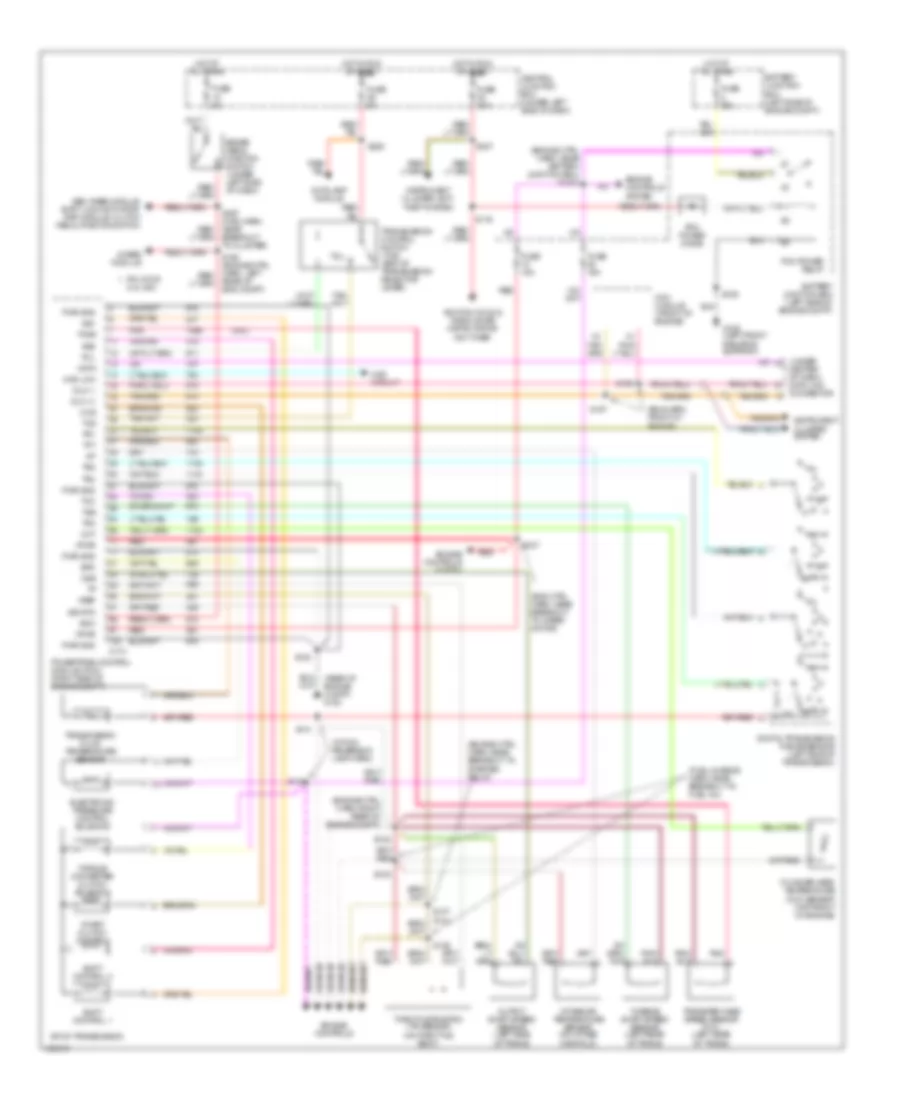
4WD Wiring Diagram, Electronic for Ford Pickup F250 Super Duty 1999
List of elements for 4WD Wiring Diagram, Electronic for Ford Pickup F250 Super Duty 1999:
- (lower right kick panel) g203
- (main harn, near breakout to gem)
- (right side of engine compt) 4x2 center axle disconnect solenoid
- (right side of engine compt) 4x4 center axle disconnect solenoid
- (under left side of dash) central junction box
- 1.1k ohms
- 3.9k ohms
- 4 wheel drive mode switch
- 4wd low out
- 4wd output
- 4x2 sol
- 4x4 high ind
- 4x4 high range indicator
- 4x4 mode sw
- 4x4 sol
- Anti-lock brake module
- Anti-lock brakes
- Apron) g105
- Batt
- Battery junction box (left side of engine compt)
- Bpp sw input
- Brake pedal position switch (under left side of dash)
- C174
- C236
- C239
- C241
- C243
- Central junction box (under left side of dash)
- Digital transmission range (dtr) sensor (left side of transmission)
- Exterior lights system
- Flasher relay
- Fuse 10a
- Fuse 30a
- Fuse 5a
- G108 (top front radiator support)
- Generic electronic module (gem) (behind left side of dash)
- H2l
- H2l rly ctrl
- Hot at all times
- Hot in run
- Illumination
- Instrument cluster
- Interior lights (instrument illumination)
- L2h
- L2h rly ctrl
- Magnetic clutch
- Neutral sw in
- Not used
- Ohms
- Powertrain control module (right side of engine compt)
- Red
- S102
- S120
- S142 (engine ctrl harn, near breakout to pwr dist box)
- S201
- S202
- S213
- S228
- S232 (main harn, near breakout to instrument cluster)
- S238
- S265
- S297
- Shift lock actuator, rear air suspension module
- Shift motor
- Sig return
- Sw a input
- Sw b input
- Sw c input
- Sw d input
- Tcec rly ctrl
- Trailer tow battery relay
- Transfer case assembly (below vehicle, behind transmission)
- Transfer case electric clutch relay (in rpo relay block)
- Transfer case shift relay module (behind center of dash)
- Wiper/washer (multi-function switch)
4WD Wiring Diagram, Mechanical for Ford Pickup F250 Super Duty 1999
List of elements for 4WD Wiring Diagram, Mechanical for Ford Pickup F250 Super Duty 1999:
- (engine ctrl harn, near breakout to pwr dist box) s142
- (main harn, near breakout to instrument cluster)
- (right side of engine compt) 4x2 center axle disconnect solenoid
- (right side of engine compt) 4x4 center axle disconnect solenoid
- 4x2
- 4x2 sol
- 4x4 high ind
- 4x4 high range indicator
- 4x4 low & high indicator switch (left side of transmission)
- 4x4 sol
- 4x4 sw in
- Anti-lock brake module
- Battery junction box (left side of engine compt)
- C174
- C236
- C241
- Central junction box (under left side of dash)
- Flasher relay
- Fuse 10a
- Fuse 30a
- Fuse 5a
- Generic electronic module (gem) (behind left side of dash)
- Hot at all times
- Hot in run
- Instrument cluster
- Magnetic clutch
- Not used
- Powertrain control module (right side of engine compt)
- Red
- S120
- S228
- S232
- S265
- Shift lock actuator, rear air suspension module
- Shift on the fly relay (in rpo relay block)
- Sotf rly ctrl
- Trailer tow battery relay
- Transfer case assembly
5.4L CNG, A/T Wiring Diagram, 4R100 for Ford Pickup F250 Super Duty 1999
List of elements for 5.4L CNG, A/T Wiring Diagram, 4R100 for Ford Pickup F250 Super Duty 1999:
- (5.4l)
- (eng ctrl harn, near breakout to wiper motor)
- (eng harn, front of engine)
- (engine ctrl harn, near battery junction box) s1003
- (engine ctrl harn, near breakout to starter relay)
- (engine ctrl harn, right rear of engine compt)
- (fuel charge harn, near breakout to fuel inj)
- (rear of engine compt) g123
- (under
- (within reversing lamp harn)
- 4r100 transmission
- 4wabs module
- 4wd circuit
- 4wd low
- Autolamp module
- Battery junction box (left side of engine compt)
- Boo
- Brake pedal position switch (under left side of dash)
- Breakout to cluster)
- C174
- Ccs
- Center of dash) data link connector
- Central junction box (under left side of dash)
- Cht
- Coast clutch control
- Cylinder head temperature (cht) sensor (top front of engine)
- Data
- Digital transmission range sensor (left side of transmission)
- Dlc (+)
- Dlc (-)
- Electronic pressure control solenoid
- Engine controls
- Engine controls system
- Epc
- Fuse 15a
- Fuse 30a
- Fuse 5a
- G108 (left front radiator support)
- Gem, rabs module, shift lock actuator, rap module, clutch pedal position switch
- Hot at all times
- Hot in run or start
- Iat
- Ignition coils & radio noise capacitor or ngv timer
- Instrument cluster system
- Instrument cluster, anti- theft system
- Intake air temperature sensor (on intake manifold)
- Ngv module (front of engine)
- Oss
- Output shaft speed sensor (left side of trans)
- Pcm power diode
- Pcm power relay
- Pin 3 for 5.4l ngv
- Pnk
- Powertrain control module (pcm) (right side of engine compt)
- Pwr gnd
- R p
- Rear of eng compt)
- Red
- S100
- S106
- S116
- S127
- S135
- S136
- S137 (5.4l)
- S138
- S140
- S141
- S156
- S157
- S225
- S237
- Shift control 1
- Shift control 2
- Sig rtn
- Ss1
- Ss2
- Tcc
- Tcil
- Tcs
- Tcss
- Tft
- Throttle position (tp) sensor (on throttle body)
- Torque converter clutch solenoid
- Tr1
- Tr2
- Tr3
- Tr4
- Transfer case speed sensor (5.4l) (left rear of trans)
- Transmission control switch (tcs) (end of transmission selector lever)
- Transmission fluid temperature sensor
- Tss
- Turbine shaft speed sensor (left rear of trans)
- Vpwr
- Vref
5.4L, A/T Wiring Diagram, 4R100 for Ford Pickup F250 Super Duty 1999
List of elements for 5.4L, A/T Wiring Diagram, 4R100 for Ford Pickup F250 Super Duty 1999:
- (5.4l)
- (eng ctrl harn, near breakout to wiper motor)
- (eng harn, front of engine)
- (engine ctrl harn, near battery junction box) s1003
- (engine ctrl harn, near breakout to starter relay)
- (engine ctrl harn, right rear of engine compt)
- (fuel charge harn, near breakout to fuel inj)
- (rear of engine compt) g123
- (under
- (within reversing lamp harn)
- 4r100 transmission
- 4wabs module
- 4wd circuit
- 4wd low
- Autolamp module
- Battery junction box (left side of engine compt)
- Boo
- Brake pedal position switch (under left side of dash)
- Breakout to cluster)
- C174
- Ccs
- Center of dash) data link connector
- Central junction box (under left side of dash)
- Cht
- Coast clutch control
- Cylinder head temperature (cht) sensor (top front of engine)
- Data
- Digital transmission range sensor (left side of transmission)
- Dlc (+)
- Dlc (-)
- Electronic pressure control solenoid
- Engine controls
- Engine controls system
- Epc
- Fuse 15a
- Fuse 30a
- Fuse 5a
- G108 (left front radiator support)
- Gem, rabs module, shift lock actuator, rap module, clutch pedal position switch
- Hot at all times
- Hot in run or start
- Iat
- Ignition coils & radio noise capacitor or ngv timer
- Instrument cluster system
- Instrument cluster, anti- theft system
- Intake air temperature sensor (on intake manifold)
- Ngv module (front of engine)
- Oss
- Output shaft speed sensor (left side of trans)
- Pcm power diode
- Pcm power relay
- Pin 3 for 5.4l ngv
- Pnk
- Powertrain control module (pcm) (right side of engine compt)
- Pwr gnd
- R p
- Rear of eng compt)
- Red
- S100
- S106
- S116
- S127
- S135
- S136
- S137 (5.4l)
- S138
- S140
- S141
- S156
- S157
- S225
- S237
- Shift control 1
- Shift control 2
- Sig rtn
- Ss1
- Ss2
- Tcc
- Tcil
- Tcs
- Tcss
- Tft
- Throttle position (tp) sensor (on throttle body)
- Torque converter clutch solenoid
- Tr1
- Tr2
- Tr3
- Tr4
- Transfer case speed sensor (5.4l) (left rear of trans)
- Transmission control switch (tcs) (end of transmission selector lever)
- Transmission fluid temperature sensor
- Tss
- Turbine shaft speed sensor (left rear of trans)
- Vpwr
- Vref
5.4L, A/T Wiring Diagram, 4R70W for Ford Pickup F250 Super Duty 1999
List of elements for 5.4L, A/T Wiring Diagram, 4R70W for Ford Pickup F250 Super Duty 1999:
- (eng ctrl harn, right rear of eng compt)
- (engine ctrl harn, near breakout to starter relay)
- (fuel charge harn, near breakout to fuel inj)
- (in reversing lamp harn)
- (rear of engine compt) g123
- (under
- 4r70w transmission (mounted under center of vehicle)
- 4wabs module
- 4wd circuit
- 4wd low
- Autolamp module
- Battery junction box (left side of engine compt)
- Boo
- Brake pedal position switch (under left side of dash)
- C174
- Center of dash) data link connector
- Central junction box (under left side of dash)
- Cht
- Cylinder head temperature (cht) sensor (top front of engine)
- Data
- Digital transmission range sensor (left side of transmission)
- Dlc (+)
- Dlc (-)
- Electronic pressure control solenoid
- Engine controls system
- Epc
- Fuse 15a
- Fuse 30a
- Fuse 5a
- G108 (left front radiator support)
- Gem, rabs module, shift lock actuator, rap module, clutch pedal position switch
- Hot at all times
- Hot in run or start
- Iat
- Ignition coils, radio noise capacitor
- Instrument cluster system
- Instrument cluster, anti- theft system
- Intake air temperature sensor (on intake manifold)
- Oss
- Output shaft speed sensor (left side of trans)
- Pcm power diode
- Pcm power relay
- Pnk
- Powertrain control module (pcm) (right side of engine compt)
- Pwr gnd
- R p
- Red
- S100
- S106
- S116
- S127 (eng ctrl harn, near breakout to wiper motor)
- S135
- S136
- S137
- S138
- S140
- S141
- S160 (engine ctrl harn, left rear of eng compt)
- S225
- S237
- S297 (main harn, near breakout to cluster)
- Shift solenoids (ss)
- Sig rtn
- Ss1
- Ss2
- Tcc
- Tcil
- Tcs
- Tcss
- Tft
- Throttle position (tp) sensor (on throttle body)
- Torque converter clutch (tcc) solenoid
- Tr1
- Tr2
- Tr3
- Tr4
- Transfer case speed sensor (left rear of trans)
- Transmission control switch (tcs) (end of transmission selector lever)
- Transmission fluid temperature sensor
- Tss
- Turbine shaft speed sensor (left rear of trans)
- Vpwr
- Vref