TRANSMISSION
3.0L
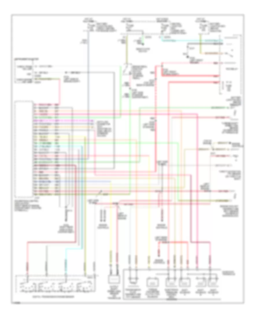
3.0L 12-Valve, A/T Wiring Diagram for Ford Taurus SES 2000

List of elements for 3.0L 12-Valve, A/T Wiring Diagram for Ford Taurus SES 2000:
- (left rear of eng compt)
- (left rear of engine)
- (left rear of engine) s105
- (top left rear of engine) s116
- (top of engine)
- Ax4s/ax4n transaxle
- Battery junction box (behind radiator)
- Battery junction box (front center of engine compt)
- Brake pedal position switch (on side of brake pedal)
- C191
- C220b
- C270a
- C270c
- Central junction box (under left side of dash)
- Check engine ind lamp c220a
- Check trans ind lamp
- Data link connector (dlc) (mounted on dash, below steering column)
- Deactivate switch
- Digital transmission range sensor
- Electronic pressure control (epc) solenoid
- Engine controls
- Engine coolant temperature (ect) sensor (on rear of engine block)
- Fuse 10a
- Fuse 15a
- Fuse 2a
- Fuse 30a
- Fuse 5a
- G100 (left front fender)
- G123 (right rear side of eng compartment)
- Hot at all times
- Hot in run or start
- Instrument cluster
- Nca
- Output shaft speed (oss) sensor (on transaxle)
- Pcm relay
- Powertrain control module (pcm) (right rear of engine compartment, mounted in firewall)
- Red
- S100
- S101
- S114
- S115 (top left side of engine)
- S117 (top of engine)
- S133
- S134 (left side of engine compt)
- S136 (left side of engine compartment)
- S137
- S140 (left front of eng compt)
- Shift solenoid a
- Shift solenoid b
- Shift solenoid c
- Throttle position (tp) sensor (on throttle body)
- Torque converter clutch (tcc) solenoid
- Transmission fluid temperature (tft) sensor
- Turbine shaft speed (tss) sensor (on rear side of transaxle)
- Vss
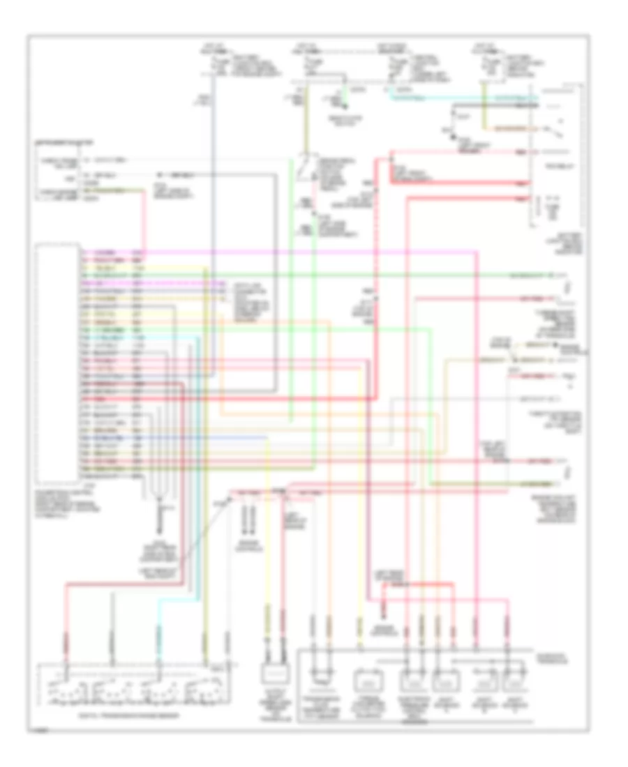
3.0L 24-Valve, A/T Wiring Diagram for Ford Taurus SES 2000
List of elements for 3.0L 24-Valve, A/T Wiring Diagram for Ford Taurus SES 2000:
- (left rear of engine)
- (left rear of engine) s104
- (left rear of engine) s105
- (left side of eng)
- (top of engine)
- Ax4s/ax4n transaxle
- Battery junction box (behind radiator)
- Battery junction box (front center of engine compt)
- Brake pedal position switch (on side of brake pedal)
- C191
- C220b
- C270a
- C270c
- Central junction box (under left side of dash)
- Check engine ind lamp c220a
- Check trans ind lamp
- Data link connector (dlc) (mounted on dash, below steering column)
- Deactivate switch
- Digital transmission range sensor
- Electronic pressure control (epc) solenoid
- Engine controls
- Engine coolant temperature (ect) sensor (on rear of engine block)
- Fuse 10a
- Fuse 15a
- Fuse 2a
- Fuse 30a
- Fuse 5a
- G100 (left front fender)
- G123 (right rear side of eng compartment)
- Hot at all times
- Hot in run or start
- Instrument cluster
- Nca
- Output shaft speed (oss) sensor (on transaxle)
- Pcm relay
- Powertrain control module (pcm) (right rear of engine compartment, mounted in firewall)
- Red
- S100
- S101
- S103 (top left rear of engine)
- S107
- S109 (left side of engine)
- S112
- S114
- S134 (left side of engine compt)
- S136 (left side of engine compartment)
- S137
- S140 (left front of eng compt)
- Shift solenoid a
- Shift solenoid b
- Shift solenoid c
- Throttle position (tp) sensor (on throttle body)
- Torque converter clutch (tcc) solenoid
- Transmission fluid temperature (tft) sensor
- Turbine shaft speed (tss) sensor (on rear side of transaxle)
- Vss
3.0L Flex Fuel, A/T Wiring Diagram for Ford Taurus SES 2000
List of elements for 3.0L Flex Fuel, A/T Wiring Diagram for Ford Taurus SES 2000:
- (left rear of eng compt)
- (left rear of engine)
- (left rear of engine) s105
- (top left rear of engine) s116
- (top of engine)
- Ax4s/ax4n transaxle
- Battery junction box (behind radiator)
- Battery junction box (front center of engine compt)
- Brake pedal position switch (on side of brake pedal)
- C191
- C220b
- C270a
- C270c
- Central junction box (under left side of dash)
- Check engine ind lamp c220a
- Check trans ind lamp
- Data link connector (dlc) (mounted on dash, below steering column)
- Deactivate switch
- Digital transmission range sensor
- Electronic pressure control (epc) solenoid
- Engine controls
- Engine coolant temperature (ect) sensor (on rear of engine block)
- Fuse 10a
- Fuse 15a
- Fuse 2a
- Fuse 30a
- Fuse 5a
- G100 (left front fender)
- G123 (right rear side of eng compartment)
- Hot at all times
- Hot in run or start
- Instrument cluster
- Nca
- Output shaft speed (oss) sensor (on transaxle)
- Pcm relay
- Powertrain control module (pcm) (right rear of engine compartment, mounted in firewall)
- Red
- S100
- S101
- S114
- S115 (top left side of engine)
- S117 (top of engine)
- S133
- S134 (left side of engine compt)
- S136 (left side of engine compartment)
- S137
- S140 (left front of eng compt)
- Shift solenoid a
- Shift solenoid b
- Shift solenoid c
- Throttle position (tp) sensor (on throttle body)
- Torque converter clutch (tcc) solenoid
- Transmission fluid temperature (tft) sensor
- Turbine shaft speed (tss) sensor (on rear side of transaxle)
- Vss