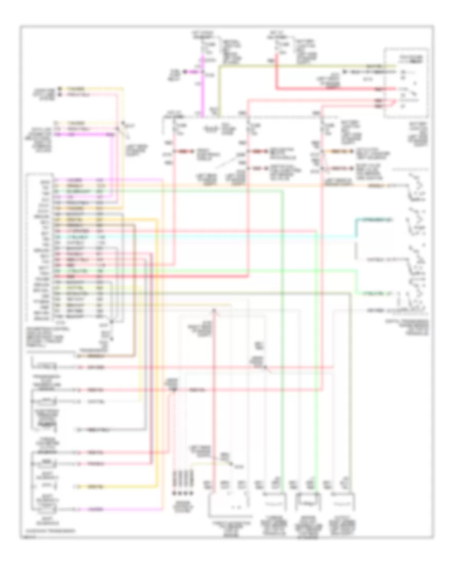
TRANSMISSION
A/T Wiring Diagram for Ford Windstar Limited 2002
List of elements for A/T Wiring Diagram for Ford Windstar Limited 2002:
- (left rear of engine compt)
- (near trans) s100
- (near trans) s101
- A/c clutch relay, canister vent solenoid
- Ax4s/ax4n transmission
- Batt
- Battery junction box (left side of engine compt)
- C175
- C270a
- Central junction box (behind left side of dash)
- Computer data lines system
- Cooling fan relays, pats module
- Data link connector (below dash, right of steering column)
- Digital transmission range sensor (on top of transaxle)
- Dlc
- Dlc(+)
- Dlc(-)
- Ect
- Electronic pressure control solenoid
- Engine controls system
- Engine coolant temperature (ect) sensor (top rear of engine)
- Epc sol
- Evap valve, egr valve, ho2 sensor, imrc monitor
- Front electronic module
- Fuel pump relay
- Fuse 10a
- Fuse 15a
- Fuse 30a
- G101 (left front of engine compt)
- G103 (on transmission)
- Ground
- Hot at all times
- Hot in run or start
- Ignition coil, fuel injectors, maf sensor, iac valve
- Oss
- Output shaft speed (oss) sensor (left side of eng compt)
- Pcm power diode
- Pcm power relay
- Power
- Powertrain control module (pcm) (behind right side of dash, through firewall)
- R p
- Red
- Return
- S102
- S103
- S105 (left side of engine compt)
- S106 (right rear of engine compt)
- S107
- S115
- S125
- S130
- S133
- S137
- S138
- S148
- Shift solenoid a
- Shift solenoid b
- Shift solenoid c
- Ss a
- Ss b
- Ss c
- Tcc
- Tft
- Throttle position (tp) sensor (top of engine)
- Torque converter clutch solenoid
- Tp sens
- Tr1
- Tr2
- Tr3a
- Tr4
- Transmission fluid temperature sensor
- Tss
- Turbine shaft speed (tss) sensor (on top of transaxle)
- Vref
 English