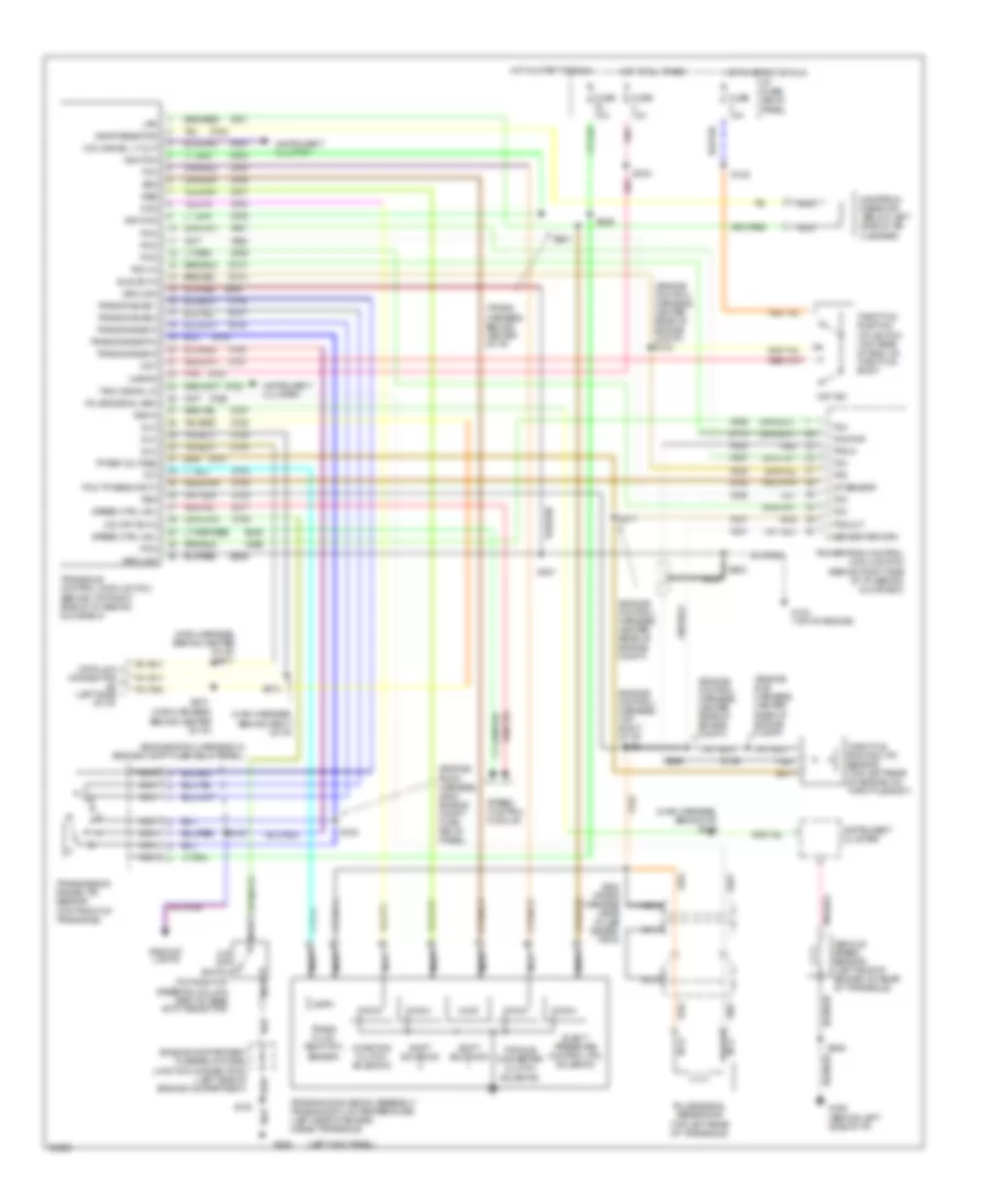
TRANSMISSION
Transmission Wiring Diagram for Mercury Villager Nautica 1996
List of elements for Transmission Wiring Diagram for Mercury Villager Nautica 1996:
- #2 (left side
- (behind top right side of i/p, behind glove box)
- (engine control harness, center rear of engine compt)
- (engine control harness, center rear of engine compt) s134
- (engine control harness, top right of i/p)
- (engine room harness, 25mm engine compt fuse relay panel)
- (engine room harness, in engine compt fuse relay panel)
- (engine sub harness, center rear of engine compt)
- (left kick panel)
- (main harness, behind center of i/p)
- (main harness, behind center of i/p) s271
- (main harness, behind i/p) s255
- (main harness, behind right of i/p)
- (top right of steering column part of gear shift selector)
- (trans harness, behind center of i/p)
- Av20
- Av21
- Av33
- Av37
- Av56
- Av57
- Av58
- Backup lights
- Ccs
- Coasting clutch solenoid
- Data link connector
- Dlc
- Drop resistor
- Dropping resistor (below left side of air cleaner)
- Ej08
- Ej17
- Elect pressure control (pc) solenoid
- Engine compartment fuse/relay panel junction connector 2 (left side of engine compartment)
- Fuse 10a
- G134 (top of engine)
- G200
- G202 (behind left side of i/p)
- Ground
- Hot at all times
- Hot in start or run
- I/p fuse/ relay panel
- Iat sensor
- Idle sw in
- Ignition
- Instrument cluster
- Kapwr
- Lps
- Nca
- O/d cancel lt out
- O/d off sw in
- O/d off switch
- Of i/p)
- Pcm
- Pcm in
- Pcm tp sens input
- Pnk
- Powertrain control module (pcm) (behind right side of i/p, behind glove box)
- Psg
- Pulse signal gen
- Pulse signal generator (top left rear of transaxle)
- Red
- S105
- S122
- S136
- S137
- S138
- S221
- S229
- S233
- S246
- S269
- S272
- S273
- S277
- S278
- S280 (trans harness near pulse gener- ator)
- S281
- S283
- Sensor
- Sensor return
- Shift solenoid
- Speed control module
- Speed ctrl mdl
- Ssa
- Ssb
- Tach signal in
- Tcc
- Tcm
- Tcm/pnp
- Throttle position (tp) sensor (top left rear of engine, on throttle body)
- Throttle position (tp) switch (top rear of eng, on throttle body)
- Torque converter clutch solenoid
- Tot
- Tp ref voltage
- Tps
- Tps in
- Tps out
- Trans fluid temp (tft)
- Trans range 1
- Trans range 2
- Trans range d
- Trans range p/n
- Trans range r
- Transaxle control module (tcm)
- Transaxle solenoid assembly/ transaxle fluid temperature (left side of engine, inside transaxle)
- Transmission range (tr) sensor (top front of transaxle)
- Vehicle speed sensor (left side of engine, on rear of transaxle)
- Vss in
- Wot
- Wot sw
- Ze15
- Ze48
- Zy01
- Zy02
- Zy03
- Zy04
- Zy05
- Zy06
- Zy07
- Zy08
- Zy09
- Zy13
- Zy14
- Zy16
- Zy17
- Zy18
- Zy19
- Zy20
- Zy21
- Zy23
- Zy24
- Zy25
- Zy27
- Zy28
- Zy29
- Zy30
- Zy31
- Zy33
- Zy34
- Zy35
- Zy39
 English