AIR CONDITIONING
A/C Wiring Diagram, Auto A/C for GMC Jimmy 1998

List of elements for A/C Wiring Diagram, Auto A/C for GMC Jimmy 1998:
- (at a/c accumulator) a/c compressor pressure cycling switch
- (body harn, below i/p fuse block) sp201
- (engine harn, in breakout to a/c compressor)
- 5 v ref
- A/c
- A/c compres- sor clutch
- A/c compres- sor clutch diode
- A/c compressor clutch relay
- A/c compressor high pressure switch (rear of compressor)
- A/c fuse 10a
- A/c pres
- A/c relay ctrl
- A/c req
- A12
- Air in
- Air temperature valve sensor and motor (top right of heater)
- Ambient air temperature sensor (right side of radiator support)
- Ambrft gnd
- Ambsen
- Automatic day- night mirror
- B12
- Battery
- Body bussed electrical center (left side of dash)
- C10
- C11
- C12
- C13
- C14
- C15
- C16
- C2 underhood bussed electrical center
- Class 2 data
- D10
- D11
- D12
- D13
- D14
- D15
- D16
- Defogger system
- Defrost
- Duct air temperature sensor (in center air duct)
- G104 (left rear of engine compt)
- G114 (left rear of engine block)
- G114 (left rear of engine)
- G201 (right side of dash)
- G202 (left side of dash)
- Ground
- H/def
- Heater
- Heater and a/c control module
- Heater and a/c solenoid assembly (behind right side of dash)
- Hot at all times
- Hot in run
- Hot in run and start
- Hvac 1 fuse 21 10a
- Hvac fuse 30a
- I/p fuse block
- Ign
- Ign e fuse 10a
- Illumination
- Inside air temperature sensor (above left front door)
- Interior lights system
- Mix fdbk
- Mix rtn
- Mode 1 drv
- Mode 2 drv
- Mode 3 drv
- Mode 4 drv
- Mode 5 drv
- Otm high
- Otm low
- Pcat sns
- Pulse width modulating blower motor (right rear of engine compt)
- Pwm
- Rdo batt fuse 19 10a
- Red
- Rr defog
- S103
- S106
- S118
- S266
- S280 (i/p harn, near breakout to radio)
- S302
- Solar sensor (top center of dash)
- Solar sns
- Sp200 (in body harness, center front of dash)
- Sp203 (i/p harness, in front of ashtray)
- Tan
- Temp motor ctrl
- Underhood bussed electrical center
- Upper discharge temperature sensor (left side of dash)
- Vehicle control module (right front of engine compt)
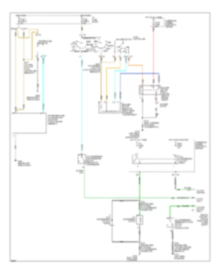
A/C Wiring Diagram, Manual A/C for GMC Jimmy 1998
List of elements for A/C Wiring Diagram, Manual A/C for GMC Jimmy 1998:
- A/c
- A/c compressor clutch
- A/c compressor clutch diode
- A/c compressor clutch relay
- A/c compressor high pressure switch (rear of a/c compressor)
- A/c compressor pressure cycling switch (at a/c accumulator)
- A/c fuse 10a
- A/c on input
- Air temperature valve electric actuator (top of heater assembly)
- Bi-lv
- Blend
- Blower motor
- Blower motor relay (center rear of engine compt)
- Blower motor resistor (right rear of engine compartment)
- Blower switch
- C tan
- Clutch control
- Cycling switch input
- Def
- G114 (left rear of engine)
- G116 (left rear of engine compartment)
- G120 (right side of engine)
- G202 (behind left side of dash)
- G203 (behind right side of dash)
- Heat
- Hot at all times
- Hot in run
- Hot in run or start
- Hvac 1 fuse 21 10a
- Hvac controller
- Hvac fuse 30a
- Hvac fuse 9 20a
- I/p fuse block
- Ign e fuse 10a
- Max
- Mode switch
- Nca
- Off
- Pickup
- Red
- S103 (engine harn, 20 cm from a/c compressor connector)
- S104 (engine harn, 20 cm from a/c compressor connector)
- S106 (engine harn, 7 cm from heated oxygen sens0r breakout)
- S118 (body harness, 25 cm from vcm breakout)
- S215 (i/p harness, 10 cm into hvac controller breakout)
- S217 (i/p harn, 6 cm into hvac controller breakout)
- Tan
- Temperature selector
- Underhood bussed electrical center
- Utilitiy
- Vehicle control module (right side of eng compt)
- Vent
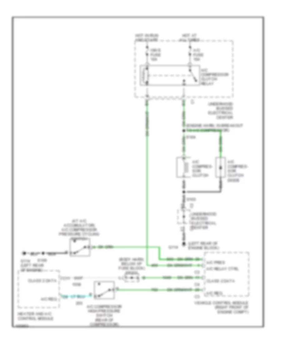
Compressor Wiring Diagram, Auto A/C for GMC Jimmy 1998
List of elements for Compressor Wiring Diagram, Auto A/C for GMC Jimmy 1998:
- (at a/c accumulator) a/c compressor pressure cycling switch
- (body harn, below i/p fuse block) sp201
- (engine harn, in breakout to a/c compressor)
- (left rear of engine block)
- A/c compres- sor clutch
- A/c compres- sor clutch diode
- A/c compressor clutch relay
- A/c compressor high pressure switch (rear of compressor)
- A/c fuse 10a
- A/c pres
- A/c relay ctrl
- A/c req
- C11
- C2 underhood bussed electrical center
- Class 2 data
- G114
- G114 (left rear of engine)
- Heater and a/c control module
- Hot at all times
- Hot in run and start
- Ign e fuse 10a
- S103
- S106
- Underhood bussed electrical center
- Vehicle control module (right front of engine compt)
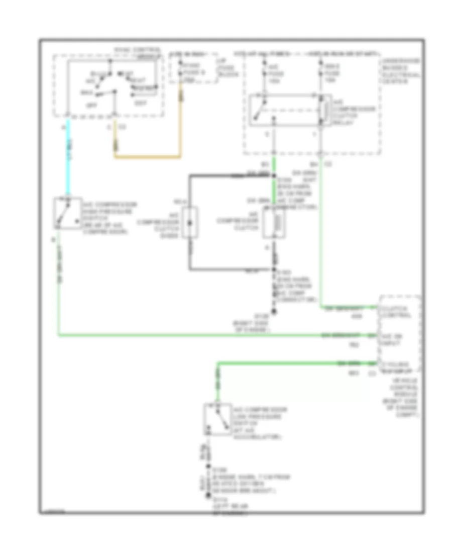
Compressor Wiring Diagram, Manual A/C for GMC Jimmy 1998
List of elements for Compressor Wiring Diagram, Manual A/C for GMC Jimmy 1998:
- A/c
- A/c compressor clutch
- A/c compressor clutch diode
- A/c compressor clutch relay
- A/c compressor high pressure switch (rear of a/c compressor)
- A/c compressor low pressure switch (at a/c accumulator)
- A/c fuse 10a
- A/c on input
- Bi-lv
- Blend
- C2 b4
- Clutch control
- Connector)
- Cycling sw input c3
- Def
- G114 (left rear of engine)
- G120 (right side of engine)
- Heat
- Heated oxygen sensor breakout)
- Hot at all times
- Hot in run
- Hot in run or start
- Hvac control module
- Hvac fuse 9 20a
- I/p fuse block
- Ign e fuse 10a
- Max
- Nca
- Off
- Underhood bussed electrical center
- Vehicle control module (right side of engine compt)
- Vent