ANTI-LOCK BRAKES
Anti-lock Brakes Wiring Diagram for GMC Cab & Chassis Sierra 3500 2004
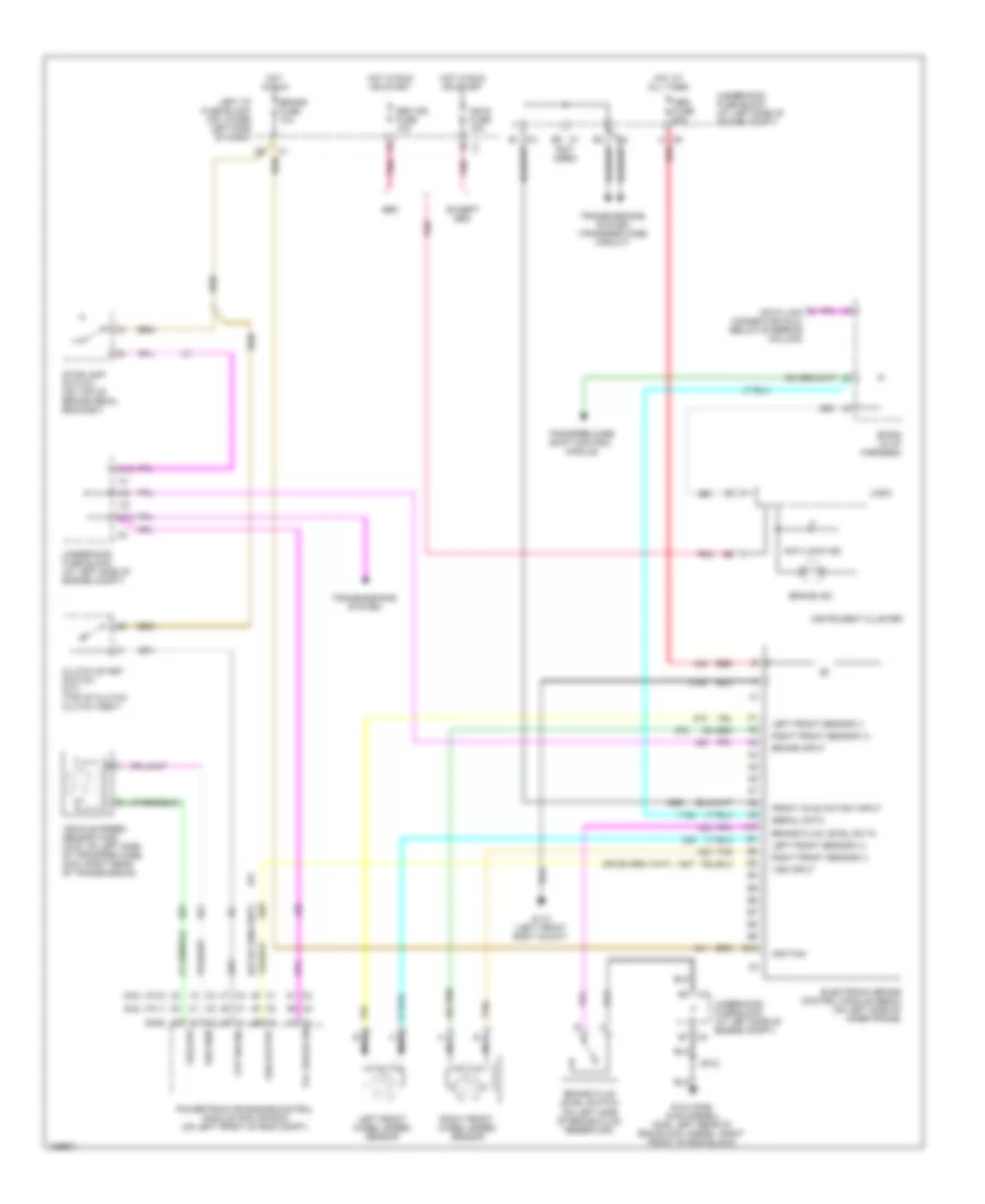
List of elements for Anti-lock Brakes Wiring Diagram for GMC Cab & Chassis Sierra 3500 2004:
- (6.6l vin 1)
- (6.6l vin 2)
- (gas)
- (not used)
- A10
- Abs fuse 60a
- Anti-lock ind
- B1 c3
- B10
- Brake fluid level sw in
- Brake fluid level switch (on left side of brake fluid reservoir)
- Brake fuse 10a
- Brake ind
- Brake input
- C12
- C2 b7
- C9 a
- Clutch start switch (m/t) (top of clutch clutch assy)
- Cpp sw sig
- Data link connector (dlc) (below steering column)
- E6 c1
- Electronic brake control module (ebcm) (on left side of inner frame)
- Except seo
- Front axle act/sw input
- G104 (gas) g106 (diesel) (gas: left rear of eng block, diesel: right front of eng block)
- G110 (left front body mount)
- Hot at all times
- Hot in run
- Hot in run or start
- Ign e fuse 10a
- Ignition
- Instrument cluster
- Left front sensor (+)
- Left front sensor (-)
- Left front wheel speed sensor
- Left i/p fuse block (on lower left side of dash)
- Logic
- Nca
- Pnk
- Powertrain or engine control module (pcm or ecm) (on left front of eng compt)
- Red
- Right front sensor (+)
- Right front sensor (-)
- Right front wheel speed sensor
- S102
- Seo
- Seo ign fuse 10a
- Serial data
- Sp205 (in i/p harness)
- Stoplamp switch (on top of brake pedal bracket)
- Tan
- Tcc brake sw
- Transfer case shift control module
- Transmissions system
- Transmissions system (transfer case circuit)
- Underhood fuse block (at left side of engine compt)
- Vehicle speed sensor (vss) (4wd: on left side of transfer case, 2wd: right rear of transmission)
- Vss high
- Vss input
- Vss low
- Vss output
 English