ANTI-LOCK BRAKES
Anti-lock Brakes Wiring Diagram (1 of 2) for Pontiac Grand Prix 2008

List of elements for Anti-lock Brakes Wiring Diagram (1 of 2) for Pontiac Grand Prix 2008:
- (3.8l)
- (3.8l: engine harness, 6.5 cm from breakout to brake fluid pressure sensor) (5.3l: engine harness, 7 cm from breakout to brake fluid pressure sensor)
- (5.3l)
- 3.8l
- 5 volt ref
- 5.3l
- A9 x1
- Abs fuse 23 fuse 10a
- Abs mtr fuse 31 fuse 40a
- Abs sol fuse 19 fuse 25a
- Abs/tcs
- Battery
- Brake pressure modulator valve (bpmv)
- Bus +
- Bus -
- C2 x4
- Delivered torque
- Electronic brake control module (ebcm) (left side of engine compt, part of brake pressure modulator valve)
- Electronic power steering system
- G115 (3.8l: lower left front of engine) (5.8l: left rear of engine)
- Gnd
- Ground
- Hot at all times
- Hot in run or start
- Ignition
- J107
- J125 (5.3l)
- Lateral acc sig
- Lf whl spd
- Lr whl spd
- Pnk
- Pump motor
- Pump motor control
- Red
- Req torque
- Rf whl spd
- Rr whl spd
- Sens sig
- Stop lamp sw
- Tan
- Underhood fuse block (mounted to right strut tower)
- Variable effort
- W/ active brake control
- W/o active brake control
- X1 f2
- X1 k1
- X4 h5
- Yaw rate sens
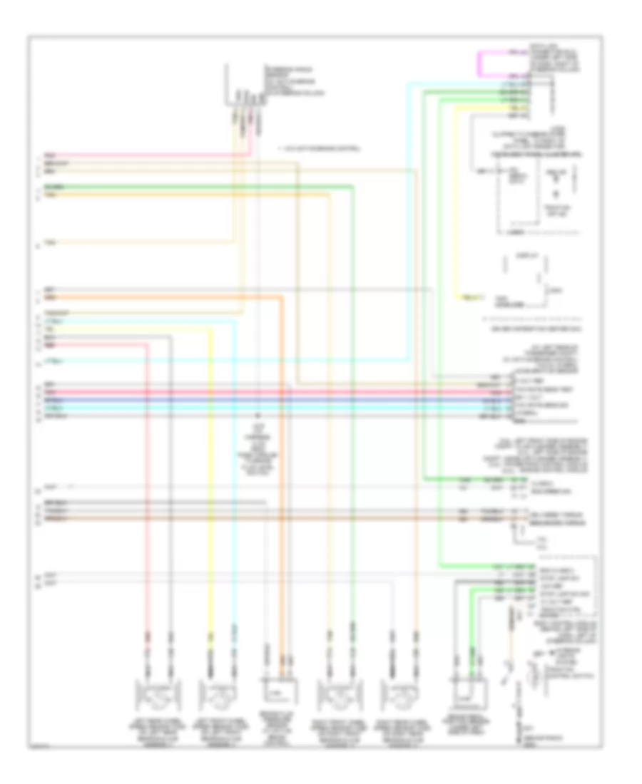
Anti-lock Brakes Wiring Diagram (2 of 2) for Pontiac Grand Prix 2008
List of elements for Anti-lock Brakes Wiring Diagram (2 of 2) for Pontiac Grand Prix 2008:
- (3.8l)
- (3.8l: left front side of engine compt, in air cleaner assembly) (5.3l: left side of engine compt, inside air cleaner assembly) powertrain control module engine control module
- (5.3l)
- (at left rear of passenger compt) (w/ active brake control) yaw & lateral acceleration sensor
- (behind radio) g200
- (under left side of dash, right of steering column)
- 10 volt ref
- 3.8l
- 5 volt ref
- 5.3l
- Abs ind
- Bcm class 2
- Body control module (behind left side of dash, left of steering column)
- Brake fluid pressure sensor (w/ active brake control)
- Brake pedal position sensor (under left side of dash)
- Bus+
- Bus-
- Class 2
- Data link connector (dlc)
- Delivered torque
- Display
- Driver information center (dic)
- Eng speed sig
- Gnd
- Ign
- Ign 1 volt
- Instrument panel cluster (ipc)
- Interior lights system
- Ipc serial data
- J216 (i/p harness, 14 cm from pass-through to brake fluid level switch)
- J231
- Jx205 (clipped to knee-bolster panel, to right of data link connector)
- Lateral
- Left front wheel speed sensor (wss) (on left front bearing & hub assembly)
- Left rear wheel speed sensor (wss) (on left rear bearing & hub assembly)
- Logic
- Low ref
- Nca
- Pnk
- Red
- Requested torque
- Right front wheel speed sensor (wss) (on right front bearing & hub assembly)
- Right rear wheel speed sensor (wss) (on right rear bearing & hub assembly)
- Steering angle sensor (w/ active brake control) (in steering column)
- Stop lamp sw
- Stop lamp sw sig
- Tan
- Traction control switch
- Traction ctrl sw sig
- Traction off ind
- Trip computer
- W/o active brake control
- Yaw rate sens sig
- Yaw rate sens test