ELECTRONIC SUSPENSION
Computer Command Ride for Pontiac Bonneville SE 1994

List of elements for Computer Command Ride for Pontiac Bonneville SE 1994:
-
-
- (below left front seat)
- (console, next to shift lever)
- 10a
- C10
- C11
- C12
- C13
- C14
- C15
- C16
- Ccr switch
- Computer command ride (ccr) controller (below left front seat)
- D10
- D11
- D12
- D13
- D14
- D15
- D16
- Data link connector (below left i/p, next to i/p fuse block)
- Diagnostic test in
- Diagnostic test out
- Firm input
- Fuse 5b
- G# n/a
- G119 (right front of engine, under electronic ignition module)
- G200 (below left side of i/p, middle of shroud)
- Ground
- Hot in run
- I/p fuse block
- Ign input
- Lateral accel sw in
- Lateral acceleration switch
- Left front strut
- Left rear strut
- Lf motor drive
- Lf position in
- Lr motor drive
- Lr position in
- Nca
- Normal input
- Perf
- Pnk
- Pos out 2
- Pos out 3
- Powertrain control module (behind right i/p, behind relay center, against bulkhead)
- Red
- Rf motor drive
- Rf position in
- Right front strut
- Right rear strut
- Rr motor drive
- Rr position in
- Tour
- Vehicle speed input
- Vehicle speed output
- Wot input
- Wot output
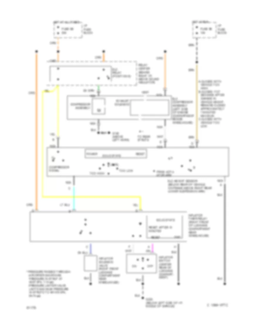
Electronic Level Control (with Assembly Inflator) for Pontiac Bonneville SE 1994
List of elements for Electronic Level Control (with Assembly Inflator) for Pontiac Bonneville SE 1994:
- * pressure passes through: -air dryer (maintains pressure in strut at 48-97 kpa, 7-14 psi) -pressure limiter valve limits maximum pressure in struts to 447-510 kpa, 64-74 psi)
- 1994 vftc c
- A-closes with vehicle too high. b-closes 17-27 seconds after change in vehicle height. remains closed approximately 7 minutes maximum. c-closes with vehicle too low.
- Compressor assembly
- Compressor signal
- Elc compressor assembly (left side of engine compartment beside wheelhouse)
- Elc height sensor (below rear of vehicle, on frame above right rear lower suspension arm)
- Elc relay (position e)
- Exhaust solenoid
- From actu- ator arm
- Fuse 5b 10a
- Fuse 9b 20a
- G100 (above left horn)
- G200 (below left side of i/p, middle of shroud)
- Gnd
- Hot at all times
- Hot in run
- I/p fuse block
- Inflator solenoid valve (right front luggage compartment near wheelhouse)
- Inflator switch (center rear of luggage compart- ment)
- Inflator timer relay (right front of luggage compartment near wheelhouse)
- Level
- Nca
- Off
- Power
- Relay center (behind right i/p, above sound insulator)
- Reset
- Reset
- Reset after 10 minutes
- Solid state
- To rear struts
- Too high
- Too low
- Vent
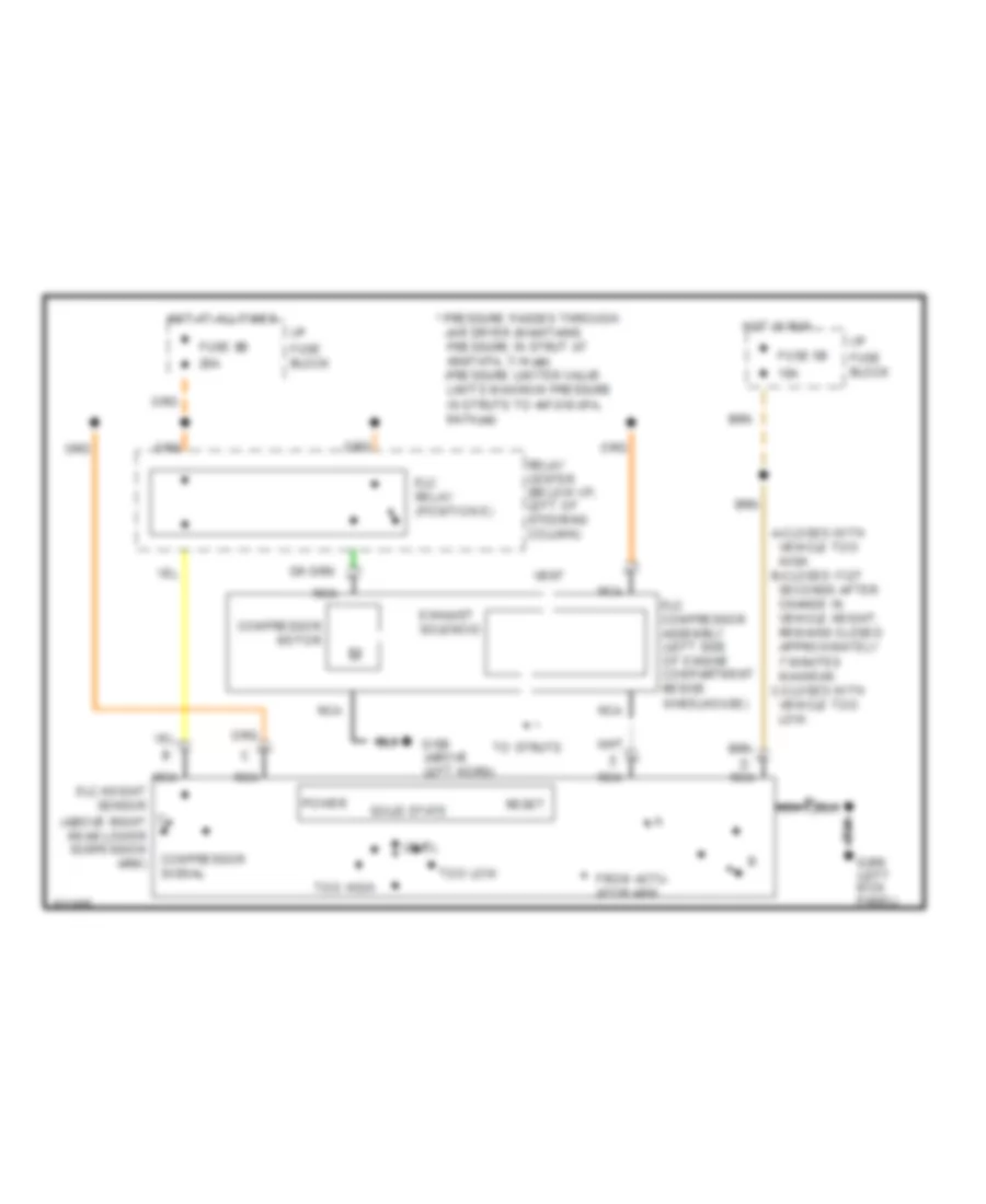
Electronic Level Control (without Assembly Inflator) for Pontiac Bonneville SE 1994
List of elements for Electronic Level Control (without Assembly Inflator) for Pontiac Bonneville SE 1994:
- to struts
- * pressure passes through: -air dryer (maintains pressure in strut at 48-97 kpa, 7-14 psi) -pressure limiter valve limits maximum pressure in struts to 447-510 kpa, 64-74 psi)
- A-closes with vehicle too high. b-closes 17-27 seconds after change in vehicle height. remains closed approximately 7 minutes maximum. c-closes with vehicle too low.
- Compressor motor
- Compressor signal
- Elc compressor assembly (left side of engine compartment beside wheelhouse)
- Elc relay (position e)
- Exhaust solenoid
- From actu- ator arm
- Fuse 5b 10a
- Fuse 9b 20a
- G100 (above left horn)
- G200 (left kick panel)
- Hot at all times
- Hot in run
- I/p fuse block
- Level
- Nca
- Nca elc height sensor (above right rear lower suspension arm)
- Power
- Relay center (below i/p, left of steering column)
- Reset
- Solid state
- Too high
- Too low
- Vent