ELECTRONIC SUSPENSION
Computer Command Ride Wiring Diagram for Pontiac Bonneville SE 1999

List of elements for Computer Command Ride Wiring Diagram for Pontiac Bonneville SE 1999:
- A pnk
- Abs/ccr fuse 5b 10a
- C10
- C11
- C12
- C13
- C14
- C15
- C16
- D10
- D11
- D12
- D13
- D14
- D15
- D16
- Data link connector (left side of dash)
- Diagnostic test in
- Diagnostic test out
- Electronic suspension control module (below left front seat)
- G111 (near battery)
- Ground
- Hot in run
- I/p fuse block (behind left side of dash)
- Ign input
- Junction connector sp215 (behind right side of dash)
- Lateral accel sw in
- Lateral accel sw out
- Lateral acceleration switch (below left front seat)
- Left front strut actuator
- Left rear strut actuator
- Lf motor drive
- Lf position in
- Lr motor drive
- Lr position in
- Perf
- Performance lamp ctrl
- Performance switch
- Pnk
- Powertrain control module (near air cleaner housing)
- Red
- Rf motor drive
- Rf position in
- Right front strut actuator
- Right rear strut actuator
- Rr motor drive
- Rr position in
- S246 (body harness, near breakout to interior lamp control module)
- S249
- S262
- S270
- S292
- Shift select switch
- Speed output
- Tour
- Touring lamp ctrl
- Touring switch
- Vehicle
- Vehicle speed input
- Wot/brake input
- Wot/brake control
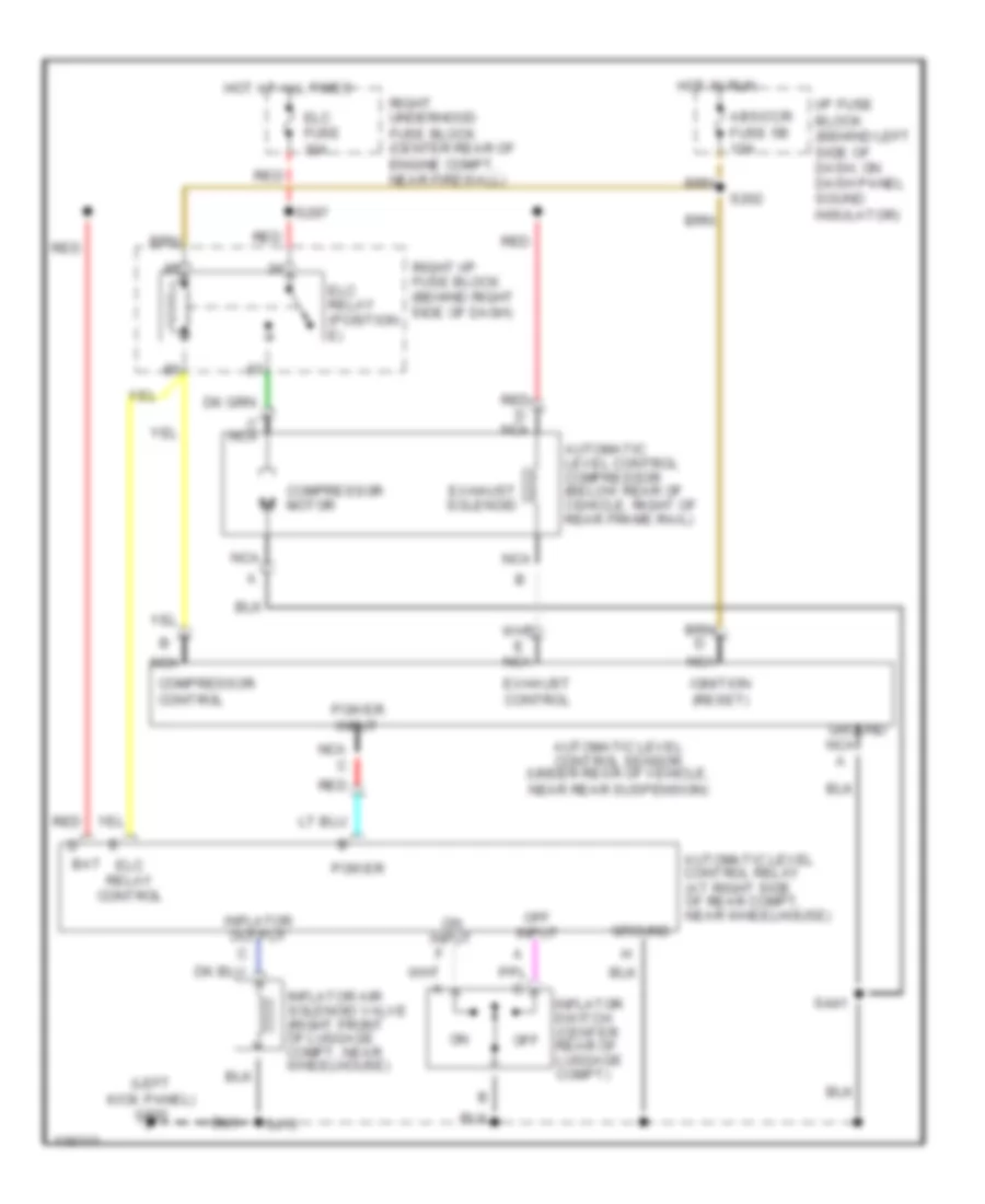
Electronic Level Control Wiring Diagram for Pontiac Bonneville SE 1999
List of elements for Electronic Level Control Wiring Diagram for Pontiac Bonneville SE 1999:
- (left kick panel) g200
- Abs/ccr fuse 5b 10a
- Automatic level control compressor (below rear of vehicle, right of rear frame rail)
- Automatic level control relay (at right side of rear compt, near wheelhouse)
- Automatic level control sensor (under rear of vehicle, near rear suspension)
- Bat
- Compressor control
- Compressor motor
- Elc fuse 30a
- Elc relay (position e)
- Elc relay control
- Exhaust control
- Exhaust solenoid
- Ground
- Hot at all times
- Hot in run
- I/p fuse block (behind left side of dash, on dash panel sound insulator)
- Ignition (reset)
- Inflator air solenoid valve (right front of luggage compt, near wheelhouse)
- Inflator output
- Inflator switch (center rear of luggage compt)
- Nca
- Nca c
- Off
- Off input
- On input
- Power
- Power input
- Red
- Right i/p fuse block (behind right side of dash)
- Right underhood fuse block (center rear of engine compt, near firewall)
- S262
- S297
- S415
- S441