ENGINE PERFORMANCE
4.3L
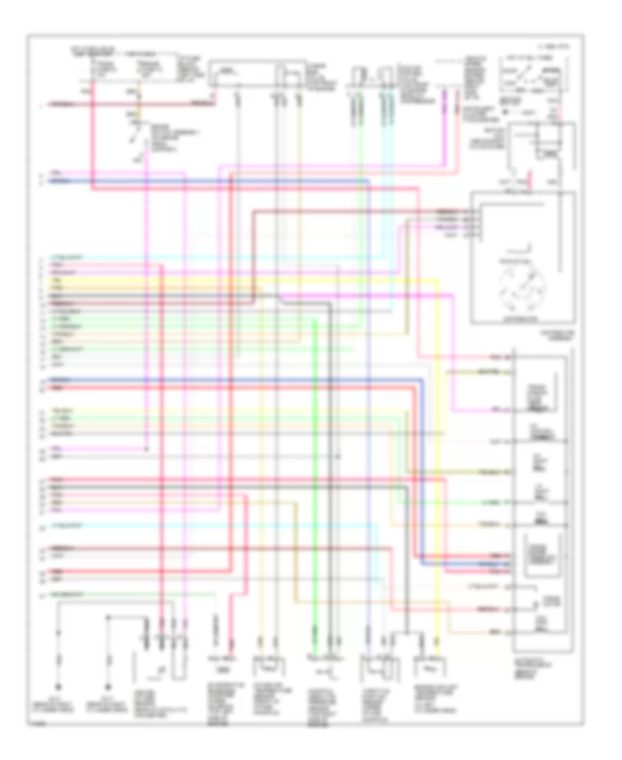
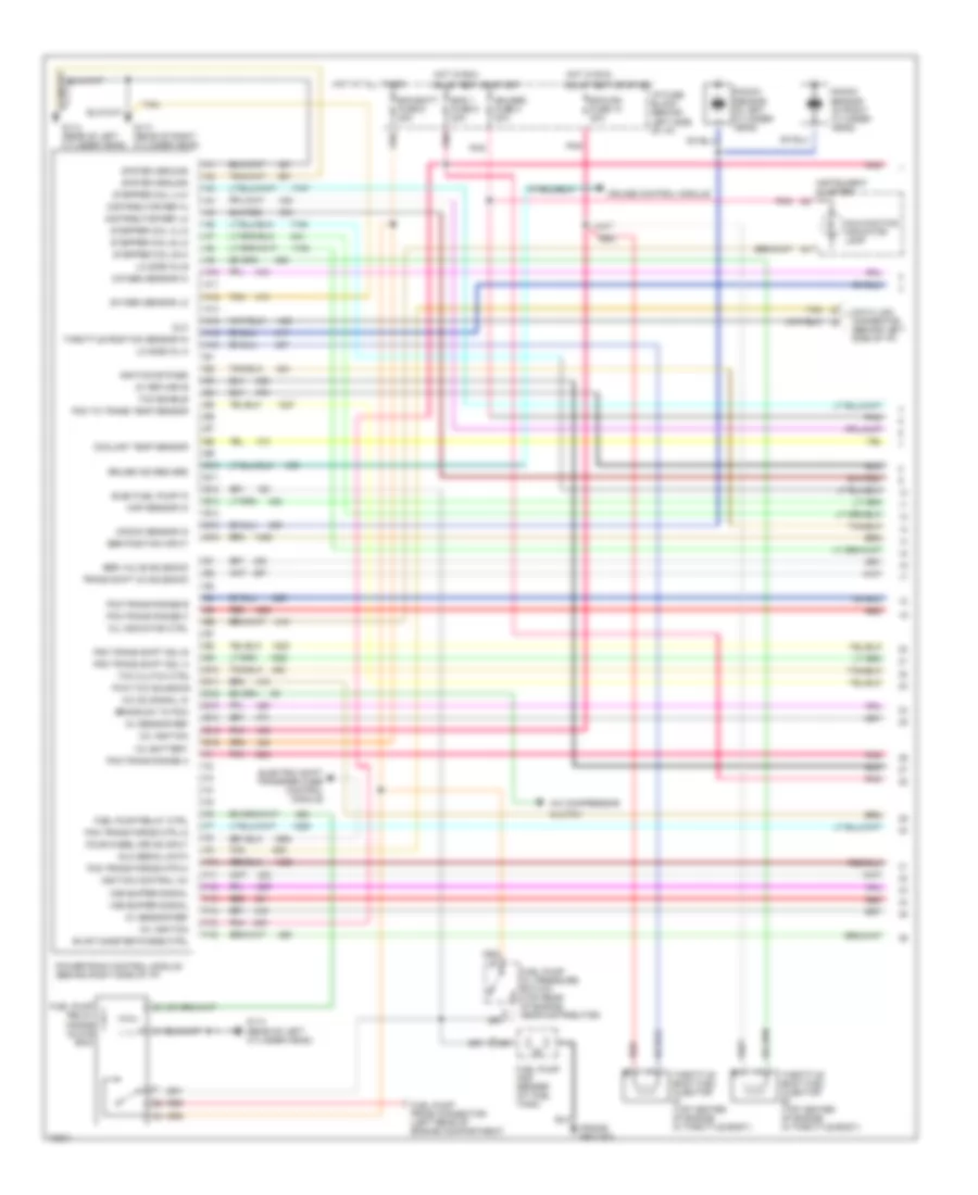
4.3L (VIN W), Engine Performance Wiring Diagrams, with PCM (1 of 2) for GMC Jimmy 1995

List of elements for 4.3L (VIN W), Engine Performance Wiring Diagrams, with PCM (1 of 2) for GMC Jimmy 1995:
- (engine compartment, right side of cowl)
- (frame ground)
- 12v battery
- 12v ignition
- 5v return b
- 5v sensor ref
- A/c compressor clutch
- A/c on signal in
- A10
- A11
- A12
- A13
- A14
- A15
- A16
- B10
- B11
- B12
- B13
- B14
- B15
- B16
- Brake sw to pcm
- Bulb test or start
- C 1995 vftc
- Coolant temp sensor
- Cruise control module
- Cruise ind reg grd
- Data link connector (behind left side of i/p)
- Distributor ref hi
- Distributor ref lo
- Dlc
- Dlc serial data
- E10
- E11
- E12
- E13
- E14
- E15
- E16
- Ecm/batt fuse 9 20a
- Ecm/ign fuse 10 20a
- Egr position input
- Egr valve solenoid
- Elec fuel pump in
- Electric shift trasfer case control module
- Eng 1 fuse 5 20a
- Evap canister purge ctrl
- F10
- F11
- F12
- F13
- F14
- F15
- F16
- Four wheel drive input
- Fuel injector (top of engine inside plenum)
- Fuel pump and sender (at fuel tank)
- Fuel pump oil pressure switch (top rear of engine, near distributor)
- Fuel pump prime connector (left rear of engine compartment)
- Fuel pump relay (inside glove box)
- Fuel pump relay ctrl
- G114 (rear of left cylinder head)
- G117 (rear of right cylinder head)
- Gauges fuse 4 20a
- Hot at all times
- Hot in run,
- I/p fuse block (behind left side of i/p)
- Iat sensor input
- Ignition bypass
- Ignition control (ic)
- Instrument cluster
- Intake manifold runner control valve (top center of intake manifold)
- Intake manifold runner control valve relay
- Knock sensor (in left cylinder head)
- Knock sensor (in right cylinder head)
- Knock sensor in
- Lo side inj a
- Malfunction indicator lamp
- Map sensor in
- Mil indicator ctrl
- Output speed
- Oxygen sensor hi
- Oxygen sensor lo
- Pcm to trans temp sensor
- Pcm trans force mtr hi
- Pcm trans force mtr lo
- Pcm trans range a
- Pcm trans range b
- Pcm trans range c
- Pcm trans shift sol a
- Pcm trans shift sol b
- Pnk
- Powertrain control module (behind right side of i/p)
- Pwm tcc solenoid
- Red
- Stepper coil a hi
- Stepper coil a lo
- Stepper coil b hi
- Stepper coil b lo
- System ground
- Tan
- Tcc clutch ctrl
- Tcc enable
- Throttle position sensor in
- Trans shift 2/3 solenoid
- Variable tuning ctrl rly
- Vss buffer signal
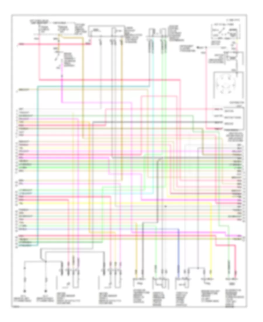
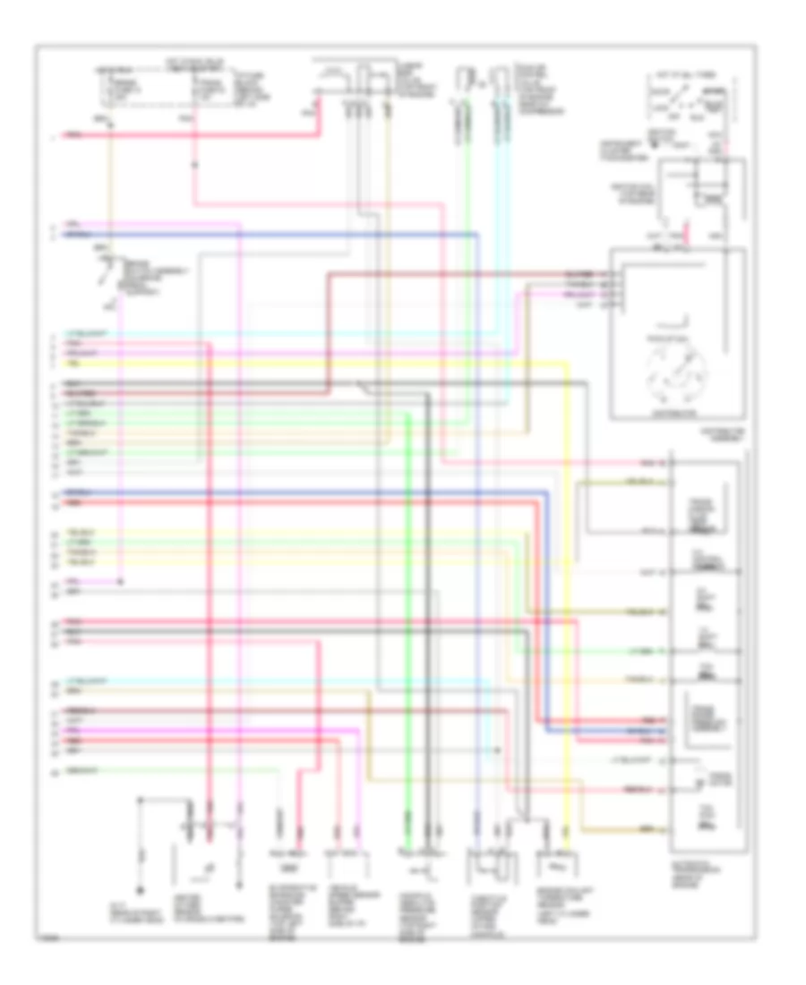
4.3L (VIN W), Engine Performance Wiring Diagrams, with PCM (2 of 2) for GMC Jimmy 1995
List of elements for 4.3L (VIN W), Engine Performance Wiring Diagrams, with PCM (2 of 2) for GMC Jimmy 1995:
- (in left cylinder head)
- (rear of engine)
- (rear of right cylinder head)
- 1-2 shift sol
- 2-3 shift sol
- 3-2 control solenoid
- Accy
- Automatic transmission
- B nca
- Brake fuse 18 20a
- Brake switch assembly (on brake pedal support)
- Bulb test
- C 1995 vftc
- C nca
- C11 red
- D nca
- Distributor
- Distributor assembly
- Engine coolant temperature sensor
- Evaporative emissions canister purge solenoid (top left side of engine)
- Force motor
- G117
- Heated oxygen sensor (rear of catalytic converter)
- Hot at all times
- Hot in run
- Hot in run, bulb test or start
- I/p fuse block (behind left side of i/p)
- Idle air control valve (top front of engine near a/c compressor)
- Ignition coil (above right valve cover)
- Ignition switch
- Instrument cluster (tachometer)
- Intake air temperature sensor (front of intake manifold)
- Linear egr valve (top front of engine)
- Lock
- Manifold absolute pressure sensor (top right side of engine)
- Nca
- Off
- Pick-up coil
- Pnk
- Red
- Run
- Start
- Tan
- Tcc pwm sol
- Tcc sol
- Throttle position sensor (upper intake manifold)
- Trans range press sw assembly
- Trans fuse 23 10a
- Trans- mission fluid temp sensor
- Vehicle speed sensor buffer (behind right side of i/p)
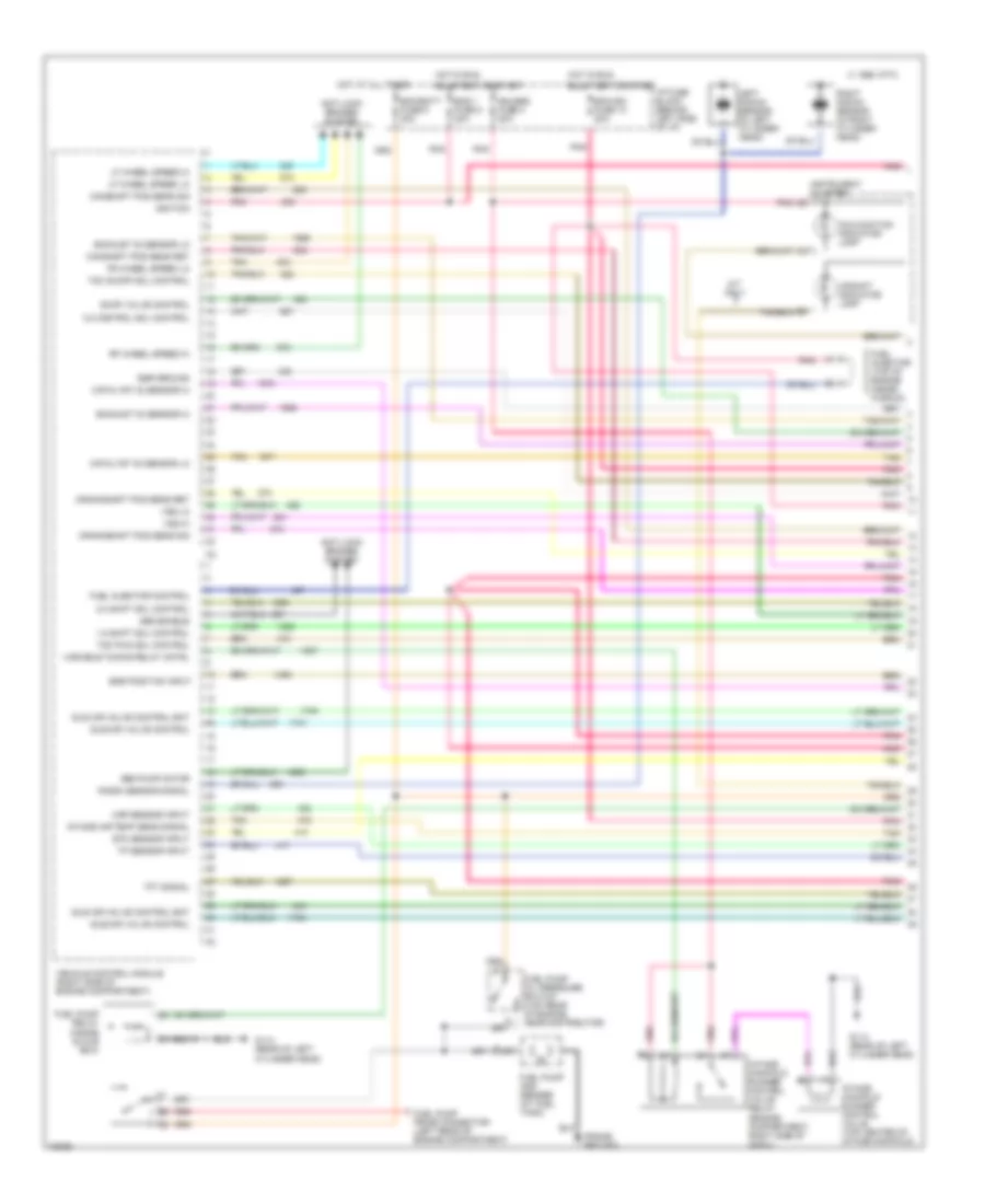
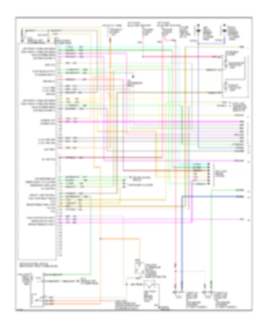
4.3L (VIN W), Engine Performance Wiring Diagrams, with VCM (1 of 3) for GMC Jimmy 1995
List of elements for 4.3L (VIN W), Engine Performance Wiring Diagrams, with VCM (1 of 3) for GMC Jimmy 1995:
- (engine compartment, right side of cowl)
- (frame ground)
- 1-2 shift sol control
- 2-3 shift sol control
- 3-2 control sol control
- Abs enable
- Abs pump motor
- Anti-lock brakes system
- Bulb test or start
- C 1995 vftc
- Camshaft pos sens ret
- Camshaft pos sens sig
- Catalyst 02 sensor hi
- Catalyst 02 sensor lo
- Crankshaft pos sens ret
- Crankshaft pos sens sig
- Ecm/batt fuse 9 20a
- Ecm/ign fuse 10 20a
- Egr ground
- Egr position input
- Eng 1 fuse 5 20a
- Etc sensor input
- Evap valve control
- Exhaust 02 sensor hi
- Exhaust 02 sensor lo
- Fr wheel speed lo
- Fuel injector (top of engine inside plenum)
- Fuel injector control
- Fuel pump and sender (at fuel tank)
- Fuel pump oil pressure switch (top rear of engine, near distributor)
- Fuel pump prime connector (left rear of engine compartment)
- Fuel pump relay (inside glove box)
- G114 (rear of left cylinder head)
- Gauges fuse 4 20a
- Hot at all times
- Hot in run,
- I/p fuse block (behind left side of i/p)
- Idle air valve control
- Idle air valve control bat
- Ignition
- Instrument cluster
- Intake air temp sens signal
- Intake manifold runner control valve (top center of intake manifold)
- Intake manifold runner control valve relay
- Knock sensor signal
- Left knock sensor (in left cylinder head)
- Lf wheel speed hi
- Lf wheel speed lo
- M/t only
- Malfunction indicator lamp
- Map sensor input
- Pnk
- Red
- Rf wheel speed hi
- Right knock sensor (in right cylinder head)
- Tan
- Tcc on/off sol control
- Tcc pwm sol control
- Tft signal
- Tp sensor input
- Upshift indicator lamp
- Variable tuning relay cntrl
- Vehicle control module (right side of engine compartment)
- Vss hi
- Vss lo
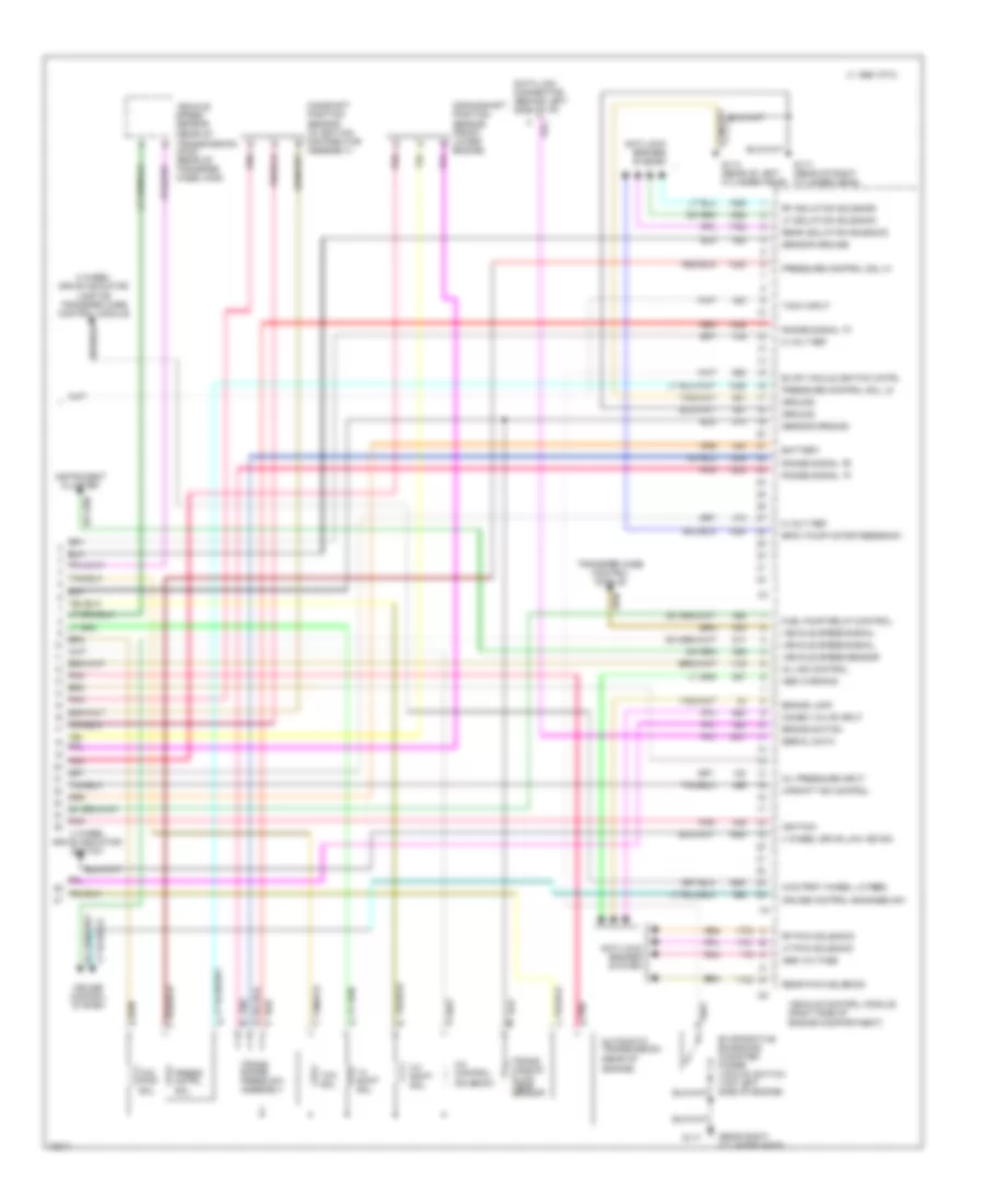
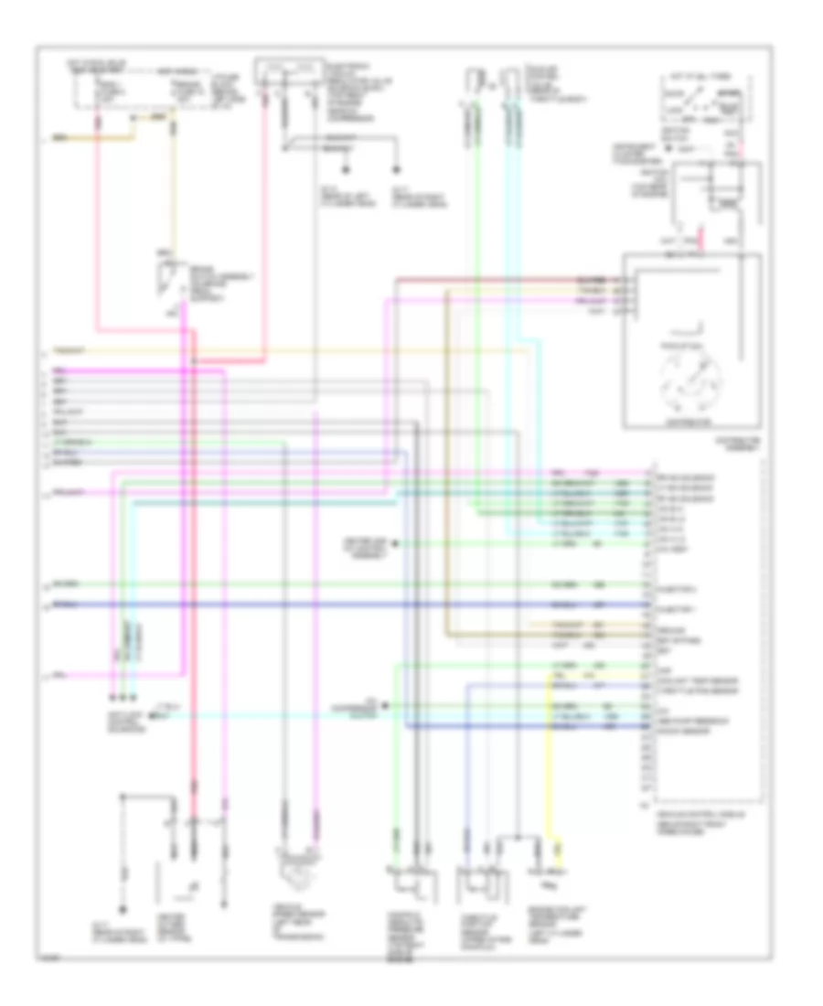
4.3L (VIN W), Engine Performance Wiring Diagrams, with VCM (2 of 3) for GMC Jimmy 1995
List of elements for 4.3L (VIN W), Engine Performance Wiring Diagrams, with VCM (2 of 3) for GMC Jimmy 1995:
- (above right valve cover)
- (in left cylinder head)
- (on brake pedal support)
- (rear of left cylinder head)
- (rear of right cylinder head)
- Acc
- B nca
- Brake fuse 18 20a
- Brake switch assembly
- Bulb test
- C 1995 vftc
- C nca
- D nca
- Distributor
- Engine coolant temperature sensor
- Evaporative emissions canister purge solenoid valve (top left side of engine)
- G114
- G117
- Ground
- Heated oxygen sensor (h02s) 1 (front of catalytic converter)
- Heated oxygen sensor (ho2s) 2 (rear of catalytic converter)
- Hot at all times
- Hot in run
- Hot in run, bulb test or start
- I/p fuse block (behind left side of i/p)
- Idle air control valve (top front of engine near a/c compressor)
- Ignition
- Ignition coil (above right valve cover)
- Ignition coil driver module
- Ignition switch
- Ignition timing
- Instrument cluster (tachometer)
- Intake air temperature sensor (front of intake manifold)
- Linear exhaust gas recirculation (egr) valve (top front of engine)
- Lock
- Manifold absolute pressure sensor (top of engine)
- Nca
- Off
- Pnk
- Pnk pnk d
- Run
- Start
- Tach signal
- Tan
- Throttle position sensor (upper intake manifold)
- Trans fuse 23 10a
4.3L (VIN W), Engine Performance Wiring Diagrams, with VCM (3 of 3) for GMC Jimmy 1995
List of elements for 4.3L (VIN W), Engine Performance Wiring Diagrams, with VCM (3 of 3) for GMC Jimmy 1995:
- (4wd)
- (rear of engine)
- (rear of transmission) (2wd) (rear of transfer case)
- (rear right cylinder head)
- 1-2 shift sol
- 2-3 shift sol
- 3-2 control solenoid
- 4 wheel drive indicator lamp or transfer case control module
- 4 wheel drive indicator switch
- 4 wheel drive low ind sig
- 4wd frnt wheel lk feed
- 5 volt ref
- Abs voltage
- Abs warning
- Anti-lock brakes system
- Automatic transmission
- Battery
- Bpmv pump motor feedback
- Brake lamp
- Brake switch
- C 1995 vftc
- C pnk
- Camshaft position sensor (in ignition distributor assembly)
- Combo valve input
- Crankshaft position sensor (front lower engine)
- Cruise control engaged sw
- Cruise control system
- Data link connector (behind left side of i/p)
- Evap vacuum switch cntrl
- Evaporative emissions canister purge vacuum switch (top left side of engine)
- Fuel pump relay control
- G114 (rear of left cylinder head)
- G117
- G117 (rear of right cylinder head)
- Ground
- Ignition
- Instrument cluster
- Lf isolation solenoid
- Lf pwm solenoid
- Mil ind control
- Oil pressure input
- Pnk
- Pnk e
- Press cntrl sol
- Pressure control sol hi
- Pressure control sol lo
- Range signal "a"
- Range signal "b"
- Range signal "c"
- Rear isolation solenoid
- Rear pwm solenoid
- Red
- Red p
- Rf isolation solenoid
- Rf pwm solenoid
- Sensor ground
- Serial data
- Tach input
- Tcc pwm sol
- Tcc sol
- Trans range press sw assembly
- Trans- mission fluid temp sensor
- Transfer case control module
- Upshift ind control
- Vehicle control module (right side of engine compartment)
- Vehicle speed sensor
- Vehicle speed signal
4.3L (VIN Z), Engine Performance Wiring Diagrams, with PCM (1 of 2) for GMC Jimmy 1995
List of elements for 4.3L (VIN Z), Engine Performance Wiring Diagrams, with PCM (1 of 2) for GMC Jimmy 1995:
- (frame ground)
- 12v battery
- 12v ignition
- 5v return b
- 5v sensor ref
- A/c compressor
- A/c on signal in
- A10
- A11
- A12
- A13
- A14
- A15
- A16
- B10
- B11
- B12
- B13
- B14
- B15
- B16
- Brake sw to pcm
- Bulb test or start
- Clutch
- Coolant temp sensor
- Cruise control module
- Cruise ind reg grd
- Data link connector (behind left side of i/p)
- Distributor ref hi
- Distributor ref lo
- Dlc
- Dlc serial data
- E10
- E11
- E12
- E13
- E14
- E15
- E16
- Ecm/batt fuse 9 20a
- Ecm/ign fuse 10 20a
- Egr position input
- Egr valve solenoid
- Elec fuel pump in
- Electric shift transfer case control module
- Eng 1 fuse 5 20a
- Evap canister purge ctrl
- F10
- F11
- F12
- F13
- F14
- F15
- F16
- Four wheel drive input
- Fuel pump and sender (at fuel tank)
- Fuel pump oil pressure switch (top rear of engine, near distributor)
- Fuel pump prime connector (left rear of engine compartment)
- Fuel pump relay (inside glove box)
- Fuel pump relay ctrl
- G114 (rear of left cylinder head)
- G117 (rear of right cylinder head)
- Gauges fuse 4 20a
- Hot at all times
- Hot in run,
- I/p fuse block (behind left side of i/p)
- Ignition bypass
- Ignition control (ic)
- Instrument cluster
- Knock sensor (in left cylinder head)
- Knock sensor (in right cylinder head)
- Knock sensor in
- Lo side inj a
- Lo side inj b
- Malfunction indicator lamp
- Map sensor in
- Mil indicator ctrl
- Oxygen sensor hi
- Oxygen sensor lo
- Pcm to trans temp sensor
- Pcm trans force mtr hi
- Pcm trans force mtr lo
- Pcm trans range a
- Pcm trans range b
- Pcm trans range c
- Pcm trans shift sol a
- Pcm trans shift sol b
- Pnk
- Powertrain control module (behind right side of i/p)
- Pwm tcc solenoid
- Red
- Stepper coil a hi
- Stepper coil a lo
- Stepper coil b hi
- Stepper coil b lo
- System ground
- Tan
- Tcc clutch ctrl
- Tcc enable
- Throttle body fuel injector #1 (top center of engine in throttle body)
- Throttle body fuel injector #2 (top center of engine in throttle body)
- Throttle position sensor in
- Trans shift 2/3 solenoid
- Vss buffer signal
4.3L (VIN Z), Engine Performance Wiring Diagrams, with PCM (2 of 2) for GMC Jimmy 1995
List of elements for 4.3L (VIN Z), Engine Performance Wiring Diagrams, with PCM (2 of 2) for GMC Jimmy 1995:
- (left cylinder head)
- (rear of engine)
- 1-2 shift sol
- 2-3 shift sol
- 3-2 control solenoid
- A pnk
- Accy
- Automatic transmission
- Brake fuse 18 20a
- Brake switch assembly (on brake pedal support)
- Bulb test
- C11
- C13
- Distributor
- Distributor assembly
- Engine coolant tmperature sensor
- Evaporative emissions canister purge solenoid (top left side of engine)
- Force motor
- G117 (rear of right cylinder head)
- Heated oxygen sensor (in cross over pipe)
- Hot at all times
- Hot in run
- Hot in run, bulb test or start
- I/p fuse block (behind left side of i/p)
- Idle air control valve (top front of engine near a/c compressor)
- Ignition coil (top rear of engine)
- Ignition switch
- Instrument cluster (tachometer)
- Linear egr valve (top front of engine)
- Lock
- Manifold absolute pressure sensor (top right side of engine)
- Nca
- Off
- Pick-up coil
- Pnk
- Red
- Run
- Start
- Tcc pwm sol
- Tcc sol
- Throttle position sensor (upper intake manifold)
- Trans range press sw assembly
- Trans fuse 23 10a
- Trans- mission fluid temp sensor
- Vehicle speed sensor buffer (behind right side of i/p)
4.3L (VIN Z), Engine Performance Wiring Diagrams, with VCM (1 of 2) for GMC Jimmy 1995
List of elements for 4.3L (VIN Z), Engine Performance Wiring Diagrams, with VCM (1 of 2) for GMC Jimmy 1995:
- (frame ground)
- 12v ign
- 12v ignition
- 5 volt ref
- 5 volt return
- A/c compressor relay
- A/c enable relay
- Abs brake warn lamp
- Abs relay
- Anti-lock brake system
- Battery
- Brake press sw input
- Brake press warn lamp
- Brake switch input
- Bulb test or start
- Cruise control module
- Cruise speed sig
- Data link connector (behind left side of i/p)
- Distributor ref hi
- Dlc
- Ecm/batt fuse 9 20a
- Ecm/ign fuse 10 20a
- Egr low
- Fuel pump and sender (at fuel tank)
- Fuel pump oil pressure switch (top rear of engine, near distributor)
- Fuel pump prime connector (engine compartment on center of cowl)
- Fuel pump relay (inside glove box)
- Fuel pump relay drive
- Fuel pump switch input
- G114 (rear of left cylinder head)
- G117 (rear of right cylinder head)
- Gauges fuse 4 20a
- Ground
- Hot at all times
- Hot in run,
- I/p fuse block (behind left side of i/p)
- Instrument cluster
- Left front wheel spd sens
- Left knock sensor (in left cylinder head)
- Malfunction indicator lamp
- Mil control
- O2 sens high
- O2 sens low
- Pnk
- Pump drive output
- Red
- Right front wheel spd sens
- Right knock sensor (in right cylinder head)
- Speed signal to cluster
- Tan
- Throttle body fuel injector #1 (top center of engine in throttle body)
- Throttle body fuel injector #2 (top center of engine in throttle body)
- Upshift indicator lamp
- Upshift lamp control
- Vehicle control module (above right front wheelhouse)
- Vehicle speed sens
4.3L (VIN Z), Engine Performance Wiring Diagrams, with VCM (2 of 2) for GMC Jimmy 1995
List of elements for 4.3L (VIN Z), Engine Performance Wiring Diagrams, with VCM (2 of 2) for GMC Jimmy 1995:
- (above right front wheelhouse)
- (left cylinder head)
- A pnk
- A/c
- A/c assy
- A/c compressor clutch
- Abs pump feedback
- Accy
- Anti-lock control solenoids
- Brake fuse 18 20a
- Brake switch assembly (on brake pedal support)
- Bulb test
- Coolant temp sensor
- Distributor
- Distributor assembly
- Electronic vacuum regulator valve solenoid (evrv) (top front of engine near a/c compressor)
- Eng 1 fuse 5 20a
- Engine coolant temperature sensor
- Est
- Est bypass
- G114 (rear of left cylinder head)
- G117 (rear of right cylinder head)
- Ground
- Heated oxygen sensor (in y-pipe)
- Heater and a/c control assembly
- Hot at all times
- Hot in run
- Hot in run, bulb test or start
- I/p fuse block (behind left side of i/p)
- Iac a hi
- Iac a lo
- Iac b hi
- Iac b lo
- Idle air control valve (rear of throttle body)
- Ignition coil (top rear of engine)
- Ignition switch
- Injector 1
- Injector 2
- Instrument cluster (tachometer)
- Knock sensor
- Lf iso solenoid
- Lock
- Manifold absolute pressure sensor (top right side of engine)
- Map
- Nca
- Off
- Pick-up coil
- Pnk
- Rf iso solenoid
- Rr iso solenoid
- Run
- Start
- Throttle pos sensor
- Throttle position sensor (upper intake manifold)
- Vehicle control module
- Vehicle speed sensor (left rear of transmission)