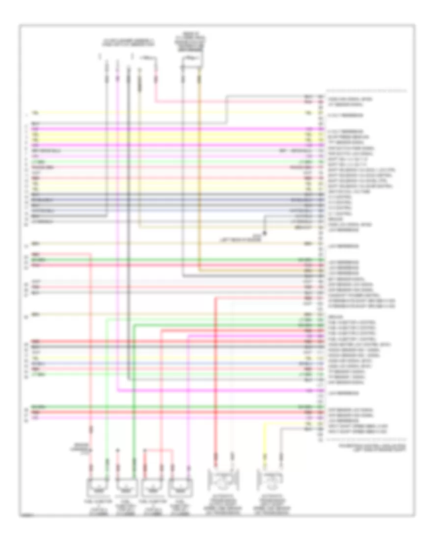
ENGINE PERFORMANCE
1.8L VIN 8
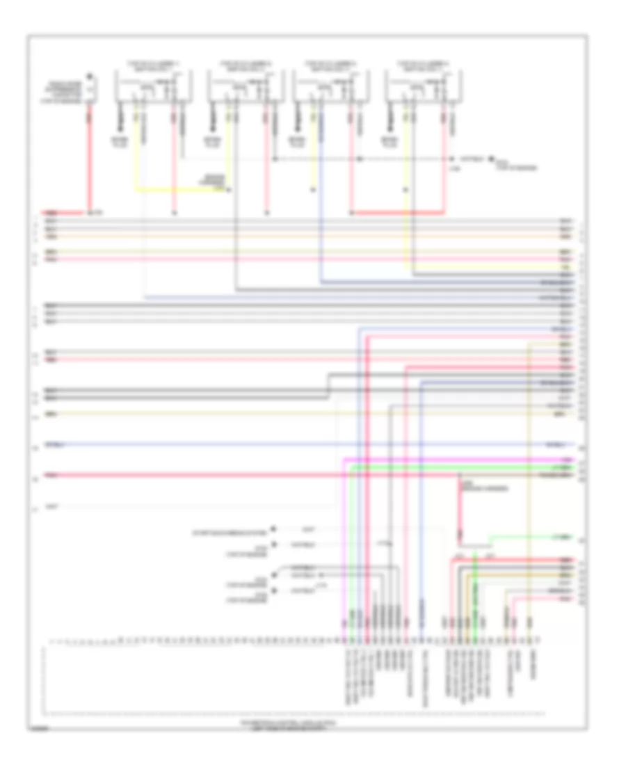
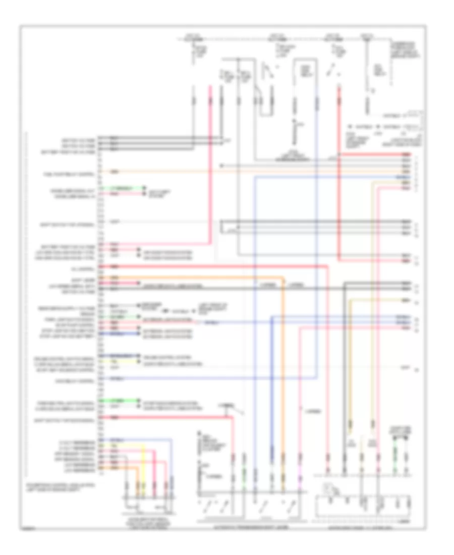
1.8L VIN 8, Engine Performance Wiring Diagram (1 of 5) for Pontiac Vibe GT 2009

List of elements for 1.8L VIN 8, Engine Performance Wiring Diagram (1 of 5) for Pontiac Vibe GT 2009:
- (left front of engine compt) g102
- 5 volt reference
- Accelerator pedal position (app) sensor (left side of dash)
- Air conditioning system
- Anti-theft system
- App sensor 1 signal
- App sensor 2 signal
- Automatic transmission shift lever position indicator
- Battery positive voltage
- Bus +
- Bus -
- Computer data lines system
- Cooling fan relay control
- Cruise control switch signal
- Cruise control system
- Defogger system
- Efi 1 fuse 10a
- Efi 2 fuse 10a
- Efi main fuse 20a
- Efi main pcb relay
- Etcs fuse 10a
- Evap pump control
- Evap vent solenoid control
- Exterior lights system
- Fuel lvl sig
- Fuel pump relay control
- G102 (left front of engine compt)
- Ground
- Hi spd gmlan serial data bus+
- Hi spd gmlan serial data bus-
- Hot at all times
- Hot in acc
- I/p junction block (right side of dash)
- Ig 2 fuse 15a
- Ig 2 pcb relay
- Ign
- Ignition voltage
- Immobilizer signal in
- Immobilizer signal out
- Instrument panel cluster (ipc)
- J101
- J104
- J114
- J117
- Logic
- Low reference
- Low speed serial data
- Main relay control
- Mil control
- Mil ind
- Park lamp switch signal
- Park/neutral switch signal
- Pnk
- Powertrain control module (pcm) (left side of engine compt)
- Red
- Shift lock relay control
- Sig (+) fuel lvl
- Starting/charging system
- Stop lamp sw sig (battery)
- Stop lamp sw sig (ignition)
- Underhood fuse block (left side of engine compt)
- W/ awd
- W/o awd
1.8L VIN 8, Engine Performance Wiring Diagram (2 of 5) for Pontiac Vibe GT 2009
List of elements for 1.8L VIN 8, Engine Performance Wiring Diagram (2 of 5) for Pontiac Vibe GT 2009:
- (engine harness) j107
- (or pnk)
- (top of cylinder 1) ignition coil 1
- (top of cylinder 2) ignition coil 2
- (top of cylinder 3) ignition coil 3
- (top of cylinder 4) ignition coil 4
- A/t
- Backup lp sw sig
- Cam phaser ctrl
- Drain wire
- Evap purge sol ctrl
- G104 (top of engine)
- G105 (top of engine)
- Ground
- Ho2s htr lo ctrl
- Ignition voltage
- J106
- J108
- J113
- J115
- J226 (engine harness)
- Low ref
- M/t
- Nca
- Pnk
- Pnp sw drive sig
- Pnp sw neutral sig
- Pnp sw second sig
- Powertrain control module (pcm) (left side of engine compt)
- Radio noise suppression capacitor (top of engine)
- Red
- Shift sol vlv slt hi
- Shift sol vlv slt lo
- Shift sol vlv slu
- Spark plug
- Starting/charging system
- Tac motor ctrl 1
- Tac motor ctrl 2
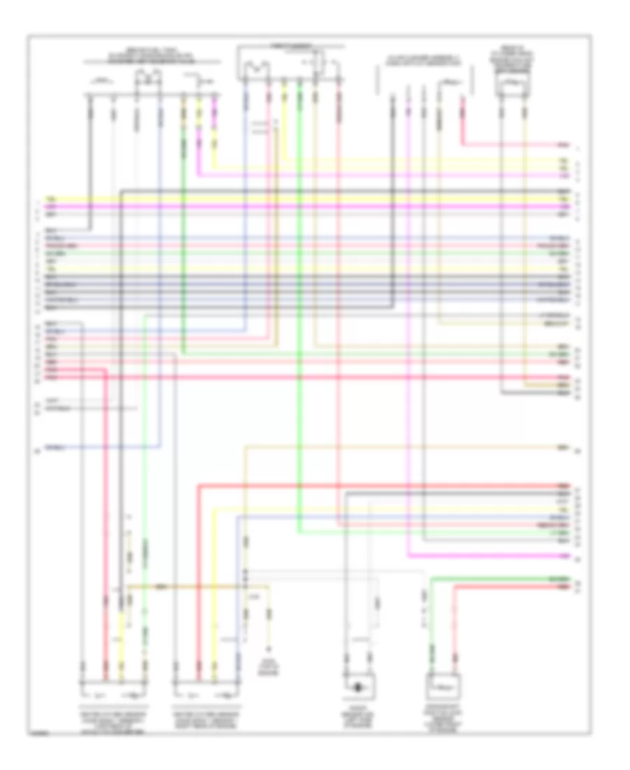
1.8L VIN 8, Engine Performance Wiring Diagram (3 of 5) for Pontiac Vibe GT 2009
List of elements for 1.8L VIN 8, Engine Performance Wiring Diagram (3 of 5) for Pontiac Vibe GT 2009:
- (engine harness) j111
- (left side of engine compt) evaporative emissions (evap) canister purge solenoid valve
- (top of fuel tank) fuel pump & sender assembly
- (top of fuel tank) secondary fuel pump & sender assembly
- Automatic transmission fluid temperature (tft) sensor
- C/opn pcb relay
- Camshaft position (cmp) actuator solenoid valve bank 2 exhaust (front of cylinder head)
- Clutch start switch (left side of dash)
- Ecu-ig 2 fuse 7 10a
- Ecu-ign 1 fuse 6 10a
- Exterior lights system
- G302 (left "c" pillar)
- Hot w/ ig 1 relay energized
- Hot w/ ig2 pcb relay energized
- I/p fuse block (left end of dash)
- Ign fuse 30 7.5a
- J116
- Left i/p junction block (left side of dash)
- Meter fuse 31 7.5a
- Park/neutral position (pnp) switch (on transmission)
- Pnk
- Red
- Shift solenoid valve (ssv) s1
- Shift solenoid valve (ssv) s2
- Shift solenoid valve (ssv) slt
- Shift solenoid valve (ssv) slu
- Shift solenoid valve (ssv) st
- Transmission connector
- W/ awd
- W/o awd
- X12
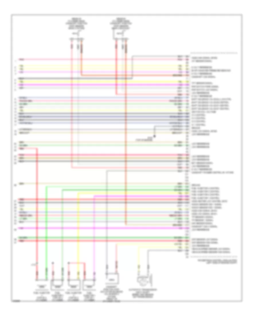
1.8L VIN 8, Engine Performance Wiring Diagram (4 of 5) for Pontiac Vibe GT 2009
List of elements for 1.8L VIN 8, Engine Performance Wiring Diagram (4 of 5) for Pontiac Vibe GT 2009:
- (behind fuel tank) evaporative emissions (evap) canister vent solenoid valve
- (in air cleaner assembly) mass air flow sensor (maf)
- (rear of cylinder head) engine coolant temperature (ect) sensor
- Crankshaft position (ckp) sensor (lower front of engine)
- G105 (top of engine)
- Heated oxygen sensor (ho2s) bank 1 sensor 1 (right rear of engine)
- Heated oxygen sensor (ho2s) bank 1 sensor 2 (upstream of catalytic converter)
- J103
- Knock sensor (ks) (left side of engine)
- Pnk
- Red
- Throttle body
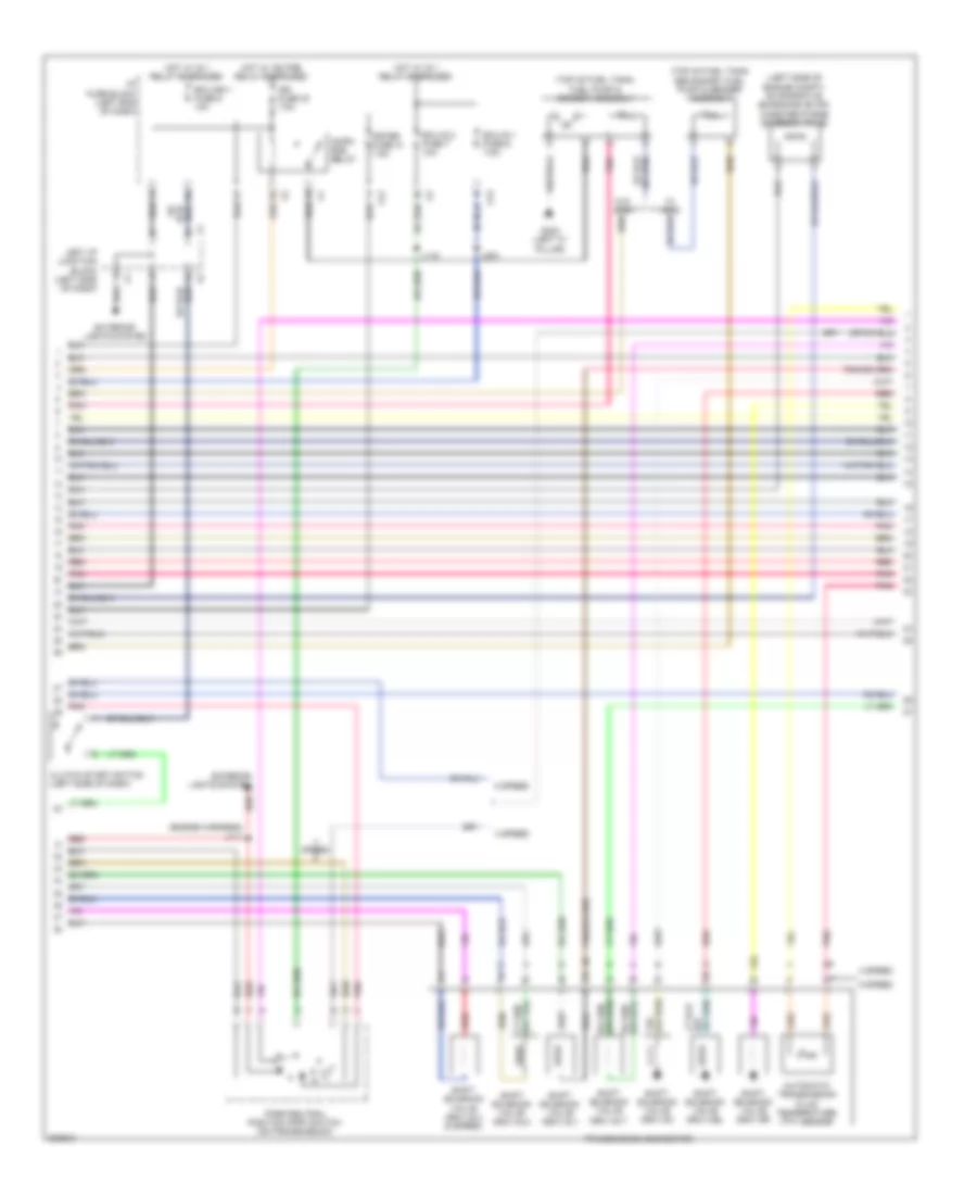
1.8L VIN 8, Engine Performance Wiring Diagram (5 of 5) for Pontiac Vibe GT 2009
List of elements for 1.8L VIN 8, Engine Performance Wiring Diagram (5 of 5) for Pontiac Vibe GT 2009:
- (rear of cylinder head) camshaft position (cmp) sensor bank 2 exhaust
- (rear of cylinder head) camshaft position (cmp) sensor bank 2 intake
- 5 volt reference
- Automatic transmission input shaft speed (iss) sensor (on transmission)
- Camshaft cam signal
- Camshaft cam x signal
- Camshaft phaser control b1 intake
- Camshaft position (cmp) actuator solenoid valve bank 2 intake (front of cylinder head)
- Ckp sensor high signal
- Ckp sensor low signal
- Ect sensor signal
- Evap canister pressure sens sig
- Fuel injector (top of 2 cylinder)
- Fuel injector (top of 4 cylinder)
- Fuel injector 1 (top of 1 cylinder)
- Fuel injector 1 control
- Fuel injector 2 control
- Fuel injector 3 (top of 3 cylinder)
- Fuel injector 3 control
- Fuel injector 4 control
- G104 (top of engine)
- Ground
- Ho2s heater low control (b1s1
- Ho2s high signal (b1s1)
- Ho2s high signal (b1s2)
- Ho2s low signal (b1s1)
- Ho2s low signal (b1s2)
- Iat sensor signal
- Ic 1 control
- Ic 2 control
- Ic 3 control
- Ic 4 control
- Ignition coil voltage
- J112
- Knock sensor (ks) 1 signal
- Low reference
- Maf sensor signal
- Pnk
- Pnp switch low signal
- Pnp switch park signal
- Powertrain control module (pcm) (left side of engine compt)
- Red
- Shift solenoid valve s1 control
- Shift solenoid valve s2 control
- Shift solenoid valve slu low ctrl
- Shift solenoid valve st control
- Tft sensor signal
- Tp sensor 1 signal
- Tp sensor 2 signal
- Vehicle speed sensor high signal
- Vehicle speed sensor low signal
2.4L VIN 0
2.4L VIN 0, Engine Performance Wiring Diagram (1 of 5) for Pontiac Vibe GT 2009
List of elements for 2.4L VIN 0, Engine Performance Wiring Diagram (1 of 5) for Pontiac Vibe GT 2009:
- (left front of engine compt) g102
- 4 speed
- 5 speed
- 5 volt reference
- Accelerator pedal position (app) sensor (left side of dash)
- Air conditioning system
- Anti-theft system
- App sensor 1 signal
- App sensor 2 signal
- Automatic transmission shift lever
- Battery positive voltage
- Bus +
- Bus -
- Computer data lines system
- Cruise control switch signal
- Cruise control system
- Defogger system
- Efi 1 fuse 10a
- Efi 2 fuse 10a
- Efi main fuse 20a
- Etcs fuse 10a
- Evap pump control
- Evap vent solenoid control
- Exterior lights system
- Fuel lvl sig
- Fuel pump relay control
- G102 (left front of engine compt)
- G201 (behind instrument cluster)
- Ground
- Hi spd gmlan serial data bus+
- Hi spd gmlan serial data bus-
- High spd cooling fan rly ctrl
- Hot at all times
- Hot in acc
- I/p junction block (right side of dash)
- Ig 2 fuse 15a
- Ig 2 pcb relay
- Ign
- Ignition voltage
- Immobilizer signal in
- Immobilizer signal out
- Instrument panel cluster (ipc)
- J101
- J104
- J114
- J117
- Logic
- Low reference
- Low spd cooling fan rly ctrl
- Low speed serial data
- Main pcb relay
- Main relay control
- Mil control
- Mil ind
- Park lamp switch signal
- Park/neutral switch signal
- Pnk
- Powertrain control module (pcm) (left side of engine compt)
- Red
- Shift lever
- Shift switch tap down signal
- Shift switch tap up signal
- Sig (+) fuel lvl
- Starting/charging system
- Stop lamp sw sig (battery)
- Stop lamp sw sig (ignition)
- Underhood fuse block (left side of engine compt)
- W/ awd
- W/o awd
2.4L VIN 0, Engine Performance Wiring Diagram (2 of 5) for Pontiac Vibe GT 2009
List of elements for 2.4L VIN 0, Engine Performance Wiring Diagram (2 of 5) for Pontiac Vibe GT 2009:
- (or pnk)
- (top of cylinder 1) ignition coil 1
- (top of cylinder 2) ignition coil 2
- (top of cylinder 3) ignition coil 3
- (top of cylinder 4) ignition coil 4
- 4 speed
- A/t
- Backup lp sw sig
- Drain wire
- Evap purge sol ctrl
- G104 (left rear of engine)
- G105 (left rear of engine)
- Generator turn on
- Ground
- Ho2s htr lo ctrl
- Ignition voltage
- J106
- J107
- J108
- J113
- J115
- J226 (engine harness)
- M/t
- Nca
- Pnk
- Pnp sw drive sig
- Pnp sw neutral sig
- Pnp sw second sig
- Powertrain control module (pcm) (left side of engine compt)
- Radio noise suppression capacitor (top of engine)
- Red
- Shift sol vlv sl1
- Shift sol vlv sl2 hi
- Shift sol vlv sl2 lo
- Shift sol vlv sl3 hi
- Shift sol vlv sl3 lo
- Spark plug
- Starting/ charging system
- Tac motor ctrl 1
- Tac motor ctrl 2
2.4L VIN 0, Engine Performance Wiring Diagram (3 of 5) for Pontiac Vibe GT 2009
List of elements for 2.4L VIN 0, Engine Performance Wiring Diagram (3 of 5) for Pontiac Vibe GT 2009:
- (engine harness) j111
- (left side of engine compt) evaporative emissions (evap) canister purge solenoid valve
- (top of fuel tank) fuel pump & sender assembly
- (top of fuel tank) secondary fuel pump & sender assembly
- 4 speed
- 5 speed
- Automatic transmission fluid temperature (tft) sensor
- C/opn pcb relay
- Clutch start switch (left side of dash)
- Ecu-ig 1 fuse 6 7.5a
- Ecu-ig 2 fuse 7 10a
- Ecu-ign 1 fuse 6 10a
- Exterior lights system
- G302 (left "c" pillar)
- Hot w/ ig 1 relay energized
- Hot w/ ig2 pcb relay energized
- I/p fuse block (left end of dash)
- Ign fuse 30 7.5a
- J116
- J203
- Left i/p junction block (left side of dash)
- Meter fuse 31 7.5a
- Park/neutral position (pnp) switch (on transmission)
- Pnk
- Red
- Shift solenoid valve (ssv) dsl
- Shift solenoid valve (ssv) s4
- Shift solenoid valve (ssv) sl1
- Shift solenoid valve (ssv) sl2
- Shift solenoid valve (ssv) sl3 (5 speed)
- Shift solenoid valve (ssv) slt
- Shift solenoid valve (ssv) sr
- Speed
- Transmission connector
- W/ awd
- W/o awd
- X12
- X13
2.4L VIN 0, Engine Performance Wiring Diagram (4 of 5) for Pontiac Vibe GT 2009
List of elements for 2.4L VIN 0, Engine Performance Wiring Diagram (4 of 5) for Pontiac Vibe GT 2009:
- (behind fuel tank) evaporative emissions (evap) canister vent solenoid valve
- (or pnk)
- Awd
- Camshaft position (cmp) actuator solenoid valve bank 2 intake (front of cylinder head)
- Camshaft position (cmp) sensor (rear of cylinder head)
- Crankshaft position (ckp) sensor (lower front of engine)
- Except awd
- G105 (left rear of engine)
- Heated oxygen sensor (ho2s) bank 1 sensor 1 (upstream of catalytic converter)
- Heated oxygen sensor (ho2s) bank 1 sensor 2 (awd: upstream of catalytic converter) (except awd: in exhaust)
- J103
- Knock sensor (ks) (left rear of engine)
- Pnk
- Red
- Throttle body
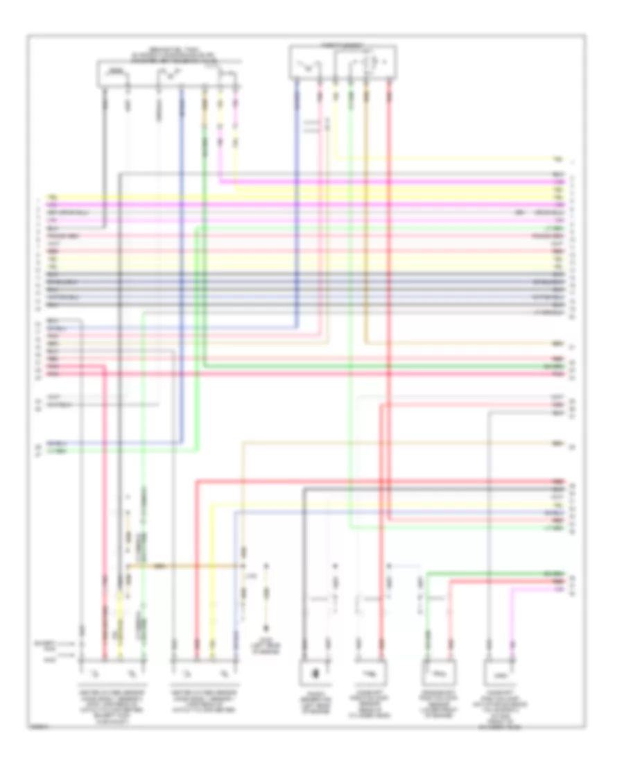
2.4L VIN 0, Engine Performance Wiring Diagram (5 of 5) for Pontiac Vibe GT 2009
List of elements for 2.4L VIN 0, Engine Performance Wiring Diagram (5 of 5) for Pontiac Vibe GT 2009:
- (engine harness) j112
- (in air cleaner assembly) mass air flow sensor (maf)
- (rear of cylinder head) engine coolant temperature (ect) sensor
- 5 volt reference
- Automatic transmission input shaft speed (iss) sensor (on transmission)
- Automatic transmission output shaft speed (oss) sensor (on transmission)
- Camshaft phaser control
- Ckp sensor high signal
- Ckp sensor low signal
- Cmp sensor high signal
- Cmp sensor low signal
- Ect sensor signal
- Evap press sens sig
- Fuel injector (top of 2 cylinder)
- Fuel injector (top of 4 cylinder)
- Fuel injector 1 (top of 1 cylinder)
- Fuel injector 1 control
- Fuel injector 2 control
- Fuel injector 3 (top of 3 cylinder)
- Fuel injector 3 control
- Fuel injector 4 control
- G104 (left rear of engine)
- Ground
- Ho2s heater low control (b1s1)
- Ho2s high signal (b1s1)
- Ho2s high signal (b1s2)
- Ho2s low signal (b1s1)
- Ho2s low signal (b1s2)
- Iat sensor signal
- Ic 1 control
- Ic 2 control
- Ic 3 control
- Ic 4 control
- Ignition coil voltage
- Input shaft speed sens hi sig
- Input shaft speed sens lo sig
- Intermediate shaft spd sen hi sig
- Knock sensor (ks) 1 signal
- Low reference
- Maf sensor signal
- Pnk
- Pnp switch low signal
- Pnp switch park signal
- Powertrain control module (pcm) (left side of engine compt)
- Red
- Shift sol vlv slt hi
- Shift sol vlv slt lo
- Shift solenoid valve dsl ctrl
- Shift solenoid valve s4 control
- Shift solenoid valve sl1 low ctrl
- Shift solenoid valve sr control
- Tft sensor signal
- Tp sensor 1 signal
- Tp sensor 2 signal