POWER DISTRIBUTION
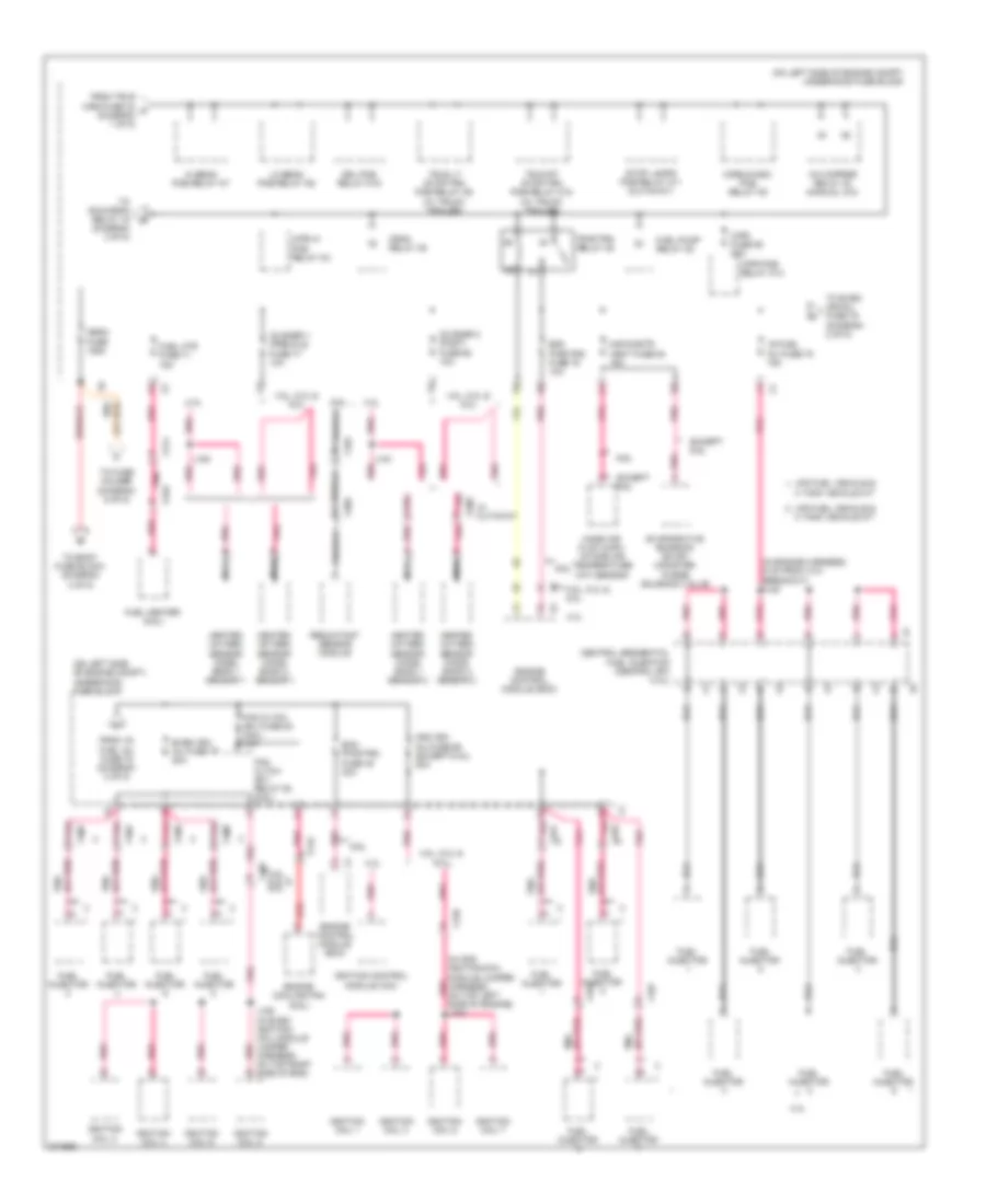
Power Distribution Wiring Diagram (1 of 5) for GMC Cutaway G3500 2012

List of elements for Power Distribution Wiring Diagram (1 of 5) for GMC Cutaway G3500 2012:
- (on left side of engine compt) underhood fuse block
- 30a
- 4.3l/ 5.3l
- 4.8l & 6.0l
- 50a
- 6.6l
- Abs mdl fuse 2 40a
- Abs mtr fuse 1 50a
- Automatic transmission
- Aux pwr outlet fuse 25 20a
- Auxiliary battery
- Auxiliary generator
- Battery
- Bcm 1 fuse 59 10a
- Bcm 2 fuse 58 15a
- Bcm 3 fuse 26 10a
- Bcm 4 fuse 9 10a
- Bcm 5 fuse 7 10a
- Bcm 6 fuse 72 10a
- Bcm 7 fuse 8 10a
- Blower motor resistor
- Body control module (bcm)
- Body fuse block (under left front seat)
- Center console 1 accessory power outlet
- Center console 2 accessory power outlet
- Cigar lighter
- Cnstr vent sol fuse 56 10a
- Control solenoid valve assembly
- Coolant heater (w/ auxiliary heater)
- Cutaway, ambulance &
- Data link connector (dlc)
- Ecm batt fuse 19 10a
- Electrical provisions
- Electronic brake control module (ebcm)
- Engine control module (ecm)
- Evaporative emission (evap) canister vent solenoid valve
- Except 6.6l
- F21
- Fcsm batt fuse 36 20a
- Foh mdl fuse 35 15a
- From cmps fuse 19 (diagram 4 of 5)
- From run relay k1 (diagram 4 of 5)
- Frt blwr fuse 74 40a
- Fuel pump flow control module (5.3l)
- Fuse 28
- Fusible link 1
- Fusible link 2
- Fusible link 3
- Fusible link 4
- Fusible link 5 (w/ dual generator 145a)
- G302 (behind left kick panel)
- G304 (behind right kick panel)
- Generator
- Glow plug control module (gpcm)
- Instrument panel cluster (ipc) (w/ odometer security wiring provision (seo))
- Intake air heater (iah)
- J247
- J249
- Ltr/dlc fuse 73 20a
- Reading lamps
- Red
- Rv upfitters
- Seo fuse 27 10a
- Starter motor
- Tcm batt fuse 32 10a
- To high beam pcb relay k7 (diagram 2 of 5)
- Trailer connector
- Transmission control module (tcm)
- Trlr wrg fuse 11 30a
- Trlr wrg fuse 42 30a
- Underhood junction block
- Upfitter aux 2
- Upftr aux 2 relay k4 (cutaway, ambulance & rv upfitters w/ multiple interior reading lamps electrical provisions)
- W/ 4 speed a/t
- W/ 6 speed a/t
- W/ active brake control
- W/ cigar lighter
- W/ cutaway upfitter
- W/ multiple interior reading lamps
- W/ rv upfitter
- W/ truck trailer
- W/o active brake control
- W/o cigar lighter
- X101
- X174
- X222
- X321
Power Distribution Wiring Diagram (2 of 5) for GMC Cutaway G3500 2012
List of elements for Power Distribution Wiring Diagram (2 of 5) for GMC Cutaway G3500 2012:
- (diagram 3 of 5)
- (in engine harness, 5 cm from x101 breakout) j120
- (in odd ignition/coil module jumper harness, on top left pnk side of engine) j184
- (on left side of engine compt) underhood fuse block
- (or red) pnk
- 3 tank vehicle kit
- 4 tank vehicle kit
- 4.3l
- 4.8l, 5.3l & 6.0l
- 6.6l
- A/c cmprsr relay 40 (manual a/c)
- Central sequential fuel injection (central sfi) (4.3l)
- Crnk relay 39
- Drl pcb relay k19
- Ecm pwr/trn fuse 45 30a
- Ecm pwr/trn fuse 78 10a
- Engine control module (ecm)
- Engine cooling fan (6.6l)
- Evaporative emission (evap) canister purge solenoid valve
- Even ign/ inj fuse 79 20a
- Except 6.6l
- Fan cltch (ev) fuse 63 (6.6l) 10a
- Fan cltch (ev) relay 50 (6.6l)
- From trlr wrg fuse 42 a (diagram 1 of 5)
- From v6 fuel inj fuse 75 (diagram 2 of 5)
- Fuel heater (6.6l)
- Fuel htr fuse 71 15a
- Fuel injector
- Fuel pump relay 38
- Heated oxygen sensor (ho2s) bank 1 sensor 1
- Heated oxygen sensor (ho2s) bank 1 sensor 2
- Heated oxygen sensor (ho2s) bank 2 sensor 1
- Heated oxygen sensor (ho2s) bank 2 sensor 2
- Hi beam pcb relay k7
- Horn/wash pcb relay k5
- Ignition coil 1
- Ignition coil 2
- Ignition coil 3
- Ignition coil 4
- Ignition coil 5
- Ignition coil 6
- Ignition coil 7
- Ignition coil 8
- Ignition control module (icm)
- J150
- J151
- J185 (in even ignition/ coil module jumper harness, on top right side of eng)
- Lo beam pcb relay k6
- Lpg fuel vehicle &
- Maf/cnstr vent fuse 64 15a
- Mass air flow (maf)/ intake air temperature (iat) sensor
- Mega fuse 125a
- Nca
- O2 snsr 1 (pre)/cls fuse 77 10a
- O2 snsr 2 (post) fuse 62 10a
- Odd ign/ inj fuse 65 (except 6.6l) 20a
- Pnk
- Pnk (or red)
- Pnk a
- Pnk b
- Pnk f
- Pwr/trn relay 49
- Red
- Reductant sensor module
- Stop lamps pcb relay k11 (cutaway)
- To body fuse block (diagram 4 of 5)
- To even ign/inj fuse 79 (diagram 2 of 5)
- To fuse holder (diagram 5 of 5)
- To run/crnk relay 15 d
- Trlr lt stop/trn pcb relay k9 (w/ truck trailer)
- Trlr rt stop/trn pcb relay k18 (w/ truck trailer)
- V6 fuel inj fuse 75 15a
- W/ cutaway
- Wpr fuse 55 25a
- Wpr hi pcb relay k3
- Wpr pcb relay k13
- X101
- X126
- X127
- X142
- X161
- X162
- X163
- X164
- X165
- X166
- X167
- X168
- X174
- X218
- X316
- X395
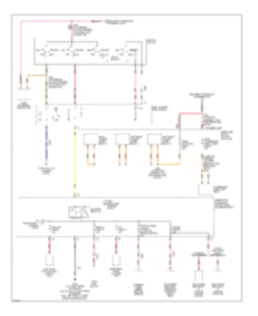
Power Distribution Wiring Diagram (3 of 5) for GMC Cutaway G3500 2012
List of elements for Power Distribution Wiring Diagram (3 of 5) for GMC Cutaway G3500 2012:
- (in prp/uf2 harness, 7 cm from breakout for rear fuse block) j312
- Acc
- Air bag fuse 28 10a
- Body control module (bcm)
- Brk sw fuse 13 10a
- Dome fluorescent work lamps fuse 2 10a
- Fluorescent work lamp relay
- From body fuse block (diagram 4 of 5)
- From mega fuse (diagram 2 of 5)
- Fscm ign fuse 6 10a
- Fuel pump flow control module (5.3l)
- G102 (4.3l: right rear of engine) (4.8l/5.3l/6.0l: on left rear of engine) (6.6l: left front lower side of engine block)
- Ign
- Ignition switch
- Inflatable restraint i/p module disable switch
- Inflatable restraint i/p module indicator
- Inflatable restraint sensing & diagnostic module (sdm)
- Instrument panel cluster (ipc)
- Ipc fuse 10 10a
- J102
- J203 (in steering column harness, 27 cm from x200 connector)
- J205 (in steering column harness, 30 cm from x200 connector)
- J302 (in prp/uf2 harness, 15 cm from rear fuse block)
- J303 (in prp/uf2 harness, 8 cm from rear fuse block)
- Key-in switch
- Left front access panel relay 5
- Left rear access panel relay 1
- Off
- Panel actuator fuse 3 45a
- Pnk
- Rear fuse block (on left "b" pillar)
- Red
- Right access panel relay 6
- Run
- Run/crnk relay 15
- Start
- Steering wheel speed/ position sensor
- Stop lamp switch
- Str/whl snsr fuse 29 (w/ active brake control) 10a
- Theft deterrent module (tdm)
- To splice j115 (diagram 5 of 5)
- To trans fuse 17 (diagram 5 of 5)
- Underhood fuse block (on left side of engine compt)
- W/ cargo lamp
- W/ manual suppression
- W/o rv upfitter & manual suppression
- X100
- X200
- X221
- X318
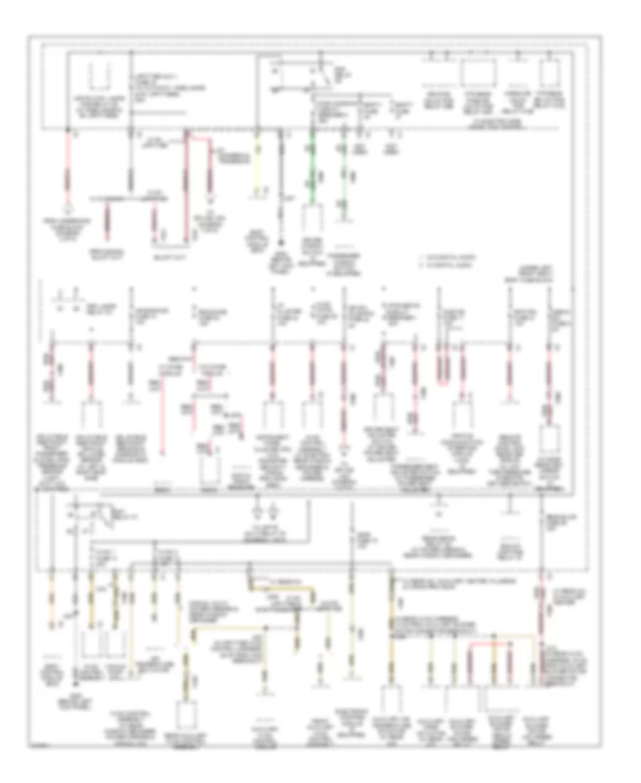
Power Distribution Wiring Diagram (4 of 5) for GMC Cutaway G3500 2012
List of elements for Power Distribution Wiring Diagram (4 of 5) for GMC Cutaway G3500 2012:
- (not used)
- (under left front seat) body fuse block
- 6.6l
- Air bag/aos fuse 10 10a
- Air temperature actuator
- Auxiliary air temperature actuator (w/ rear a/c)
- Auxiliary blower motor high speed relay
- Auxiliary blower motor low speed relay
- Auxiliary blower motor medium speed relay
- Auxiliary hvac control module
- Auxiliary mode actuator (w/ rear a/c)
- Bck/up lamp pcb relay k7
- Body control module (bcm)
- Cargo dr unlck pcb relay k10b
- Cmps fuse 19 10a
- Digital radio receiver
- Driver seat adjuster switch (w/ driver power seat adjuster)
- Driver window switch (if equipped)
- Drvr dr unlck pcb relay k9b
- Electronic compass module (if equipped)
- Empty fuse
- From underhood fuse block (diagram 2 of 5)
- Front auxiliary hvac control assembly
- Ftr rear dr lck pcb relay k10a
- Ftr rear pass dr unlck pcb relay k9a
- G302 (behind left kick panel)
- Hvac 1 fuse 14 20a
- Hvac 2 fuse 13 10a
- Hvac cntrl fuse 25 10a
- Hvac control assembly
- Hvac control assembly (w/ electric rear window defogger & power mirrors)
- Hvac control assembly (w/ rear window defogger, power mirrors & manual a/c)
- I/p cluster fuse 23 10a
- Ign sw (dlis)/pk3 fuse 22 2a
- Inflatable restraint front passenger system (pps) presence sensor (light duty w/o rv upfitter)
- Inflatable restraint sensing & diagnostic module (sdm)
- Inflatable restraint vehicle rollover sensor (w/ left & right roof side)
- Instrument panel cluster (ipc) (w/o odometer security wiring provision (seo))
- J247
- J270
- J307 (in upfitter hvac control harness, 88 cm from x303 breakout)
- J405
- J412 (in rear hvac harness, 20 cm from auxiliary blower motor connector breakout)
- Manual a/c w/ power mirrors & rear window defogger
- Onstar fuse 11 10a
- Osrvm sw fuse 9 5a
- Outside rearview mirror switch (if equipped)
- Passenger seat adjuster switch (w/ passenger power seat adjuster)
- Passenger window switch (if equipped)
- Prk lamps relay k3
- Pwr seats circuit breaker 1 30a
- Pwr windows circuit breaker 2 25a
- Radio
- Rap relay k6
- Rdo/chime fuse 20 15a
- Rear auxiliary hvac control assembly
- Rear blwr fuse 29 30a
- Rear defog relay k5 (w/ power mirror & rear window defogger)
- Remote control door lock receiver (rcdlr) (w/ low tire pressure & remote keyless entry)
- Rfa/tpm fuse 21 10a
- Run relay k1
- To splice j203 (diagram 3 of 5)
- To splice j302 (diagram 3 of 5)
- To upftr aux 2 relay k4 (diagram 1 of 5)
- Upfitter aux 1 fuse 16 (w/ cutaway, ambulance & rv upfitters) 50a
- Upftr ctsy lamps pcb relay k8 (w/ ambulance & rv upfitters)
- Vacuum pump (6.6l)
- Vehicle communication interface module (vcim) (if equipped)
- W/ chime module
- W/ commercial tradesman
- W/ cutaway
- W/ digital audio
- W/ electric side door lock control
- W/ rear a/c
- W/ rear a/c & auxiliary heater
- W/ rear a/c, auxiliary heater, plumbing & wiring provision
- W/ rv upfitter
- W/ rv upfitter & swb passenger
- W/o chime module
- W/o digital audio
- W/o rv upfitter
- X100
- X200
- X205
- X222
- X306
- X307
- X321
- X407
- X409
- X420
- X500
- X600
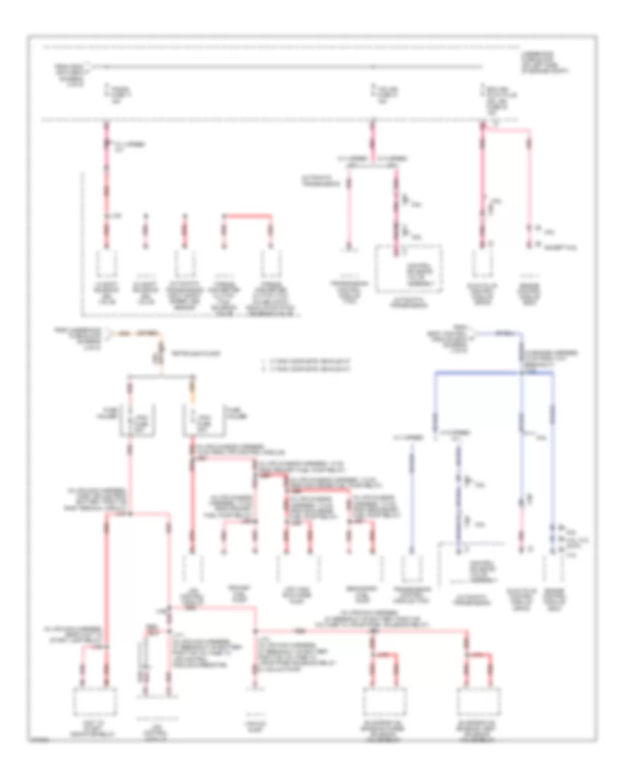
Power Distribution Wiring Diagram (5 of 5) for GMC Cutaway G3500 2012
List of elements for Power Distribution Wiring Diagram (5 of 5) for GMC Cutaway G3500 2012:
- (diagram 2 of 5)
- (in engine harness, 15 cm from x101 breakout) j115
- (in lpg chassis harness, 13 cm from lpg control module) j361
- (in lpg chassis harness, 13 cm from primary fuel pump relay) j364
- (in lpg chassis harness, 7.5 cm from primary fuel pump relay) j363
- (in lpg chassis harness, 7.5 cm from scavenge fuel pump relay) j366
- (in lpg chassis harness, 7.5 cm from scavenge red
- (in lpg chassis harness, 7.5 cm from secondary fuel pump relay) j367
- (in lpg main harness,
- (in lpg main harness, first splice from battery positive ring terminal circuit) j167
- (in lpg main harness, near wait to start lamp relay) j168
- (or red)
- 1-2 shift solenoid (ss) valve
- 2-3 shift solenoid (ss) valve
- 3 tank complete vehicle kit
- 4 tank complete vehicle kit
- 4.3l
- 4.8l, 5.3l & 6.0l
- 6.6l
- At breakout of battery positive voltage to lpg bypass solenoid relay) j172
- Automatic transmission
- Automatic transmission input shaft speed (iss) sensor
- Control solenoid valve assembly
- Ecm ign/ glow plug mdl ign fuse 30 15a
- Engine control module (ecm)
- Evaporative emission purge solenoid valve relay
- Evaporative emission vent solenoid valve relay
- Except 6.6l
- From body control h module (bcm) (diagram 3 of 5)
- From fscm j ign fuse 6 (diagram 3 of 5)
- From underhood fuse block l
- Fuel pump relay) j365
- Fuse holder
- Glow plug control module (gpcm)
- J135
- J169
- J170 (in lpg main harness, at breakout of battery positive voltage to lpg bypass solenoid relay & vacuum pump)
- J171 (in lpg main harness, at breakout of battery positive voltage to lpg control module & resistor)
- J173
- J174
- Lpcm fuse 20a
- Lpcm fuse 30a
- Lpg control module
- Lpg tank scavange pump
- M pnk
- Petroleum & gas
- Pnk
- Primary fuel pump
- Red
- Secondary fuel pump
- Tcm ign fuse 31 15a
- Torque converter clutch (tcc) pulse width modulation (pwm) solenoid valve
- Torque converter clutch (tcc) solenoid valve
- Trans fuse 17 15a
- Transmission control module (tcm)
- Underhood fuse block (on left side of engine compt)
- Vacuum pump
- W/ 4 speed
- W/ 4 speed a/t
- W/ 6 speed a/t
- Wait to start indicator relay
- X101
- X107
- X174