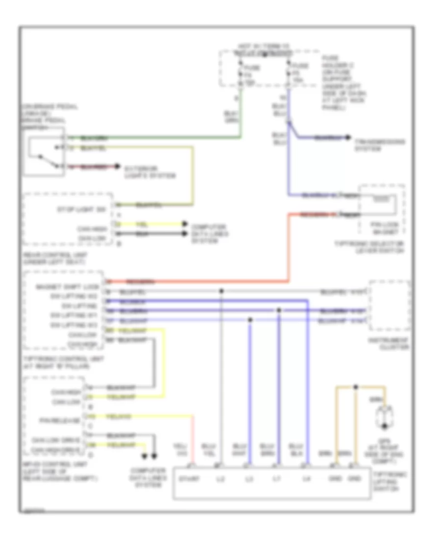
SHIFT INTERLOCK
Shift Interlock Wiring Diagram for Porsche Boxster 2005
List of elements for Shift Interlock Wiring Diagram for Porsche Boxster 2005:
- (on brake pedal linkage) brake pedal switch
- A12
- A13
- A14
- Can high
- Can high drive
- Can low
- Can low drive
- Computer data lines system
- Exterior lights system
- Fuse f4 10a
- Fuse f5 15a
- Fuse holder c (on fuse support, under left side of dash, at left kick panel)
- Gnd
- Gp9 (at right side of eng compt)
- Hot w/ term 15 relay energized
- Instrument cluster
- Magnet shift lock
- Mfi-di control unit (left side of rear luggage compt)
- Nca
- P/n lock magnet
- P/n release
- Rear control unit (under left seat)
- Start
- Stop light sw
- Sw lifting
- Sw lifting w1
- Sw lifting w2
- Sw lifting w3
- Tiptronic control unit (at right "b" pillar)
- Tiptronic lifting switch
- Tiptronic selector lever switch
- Transmissions system
 English