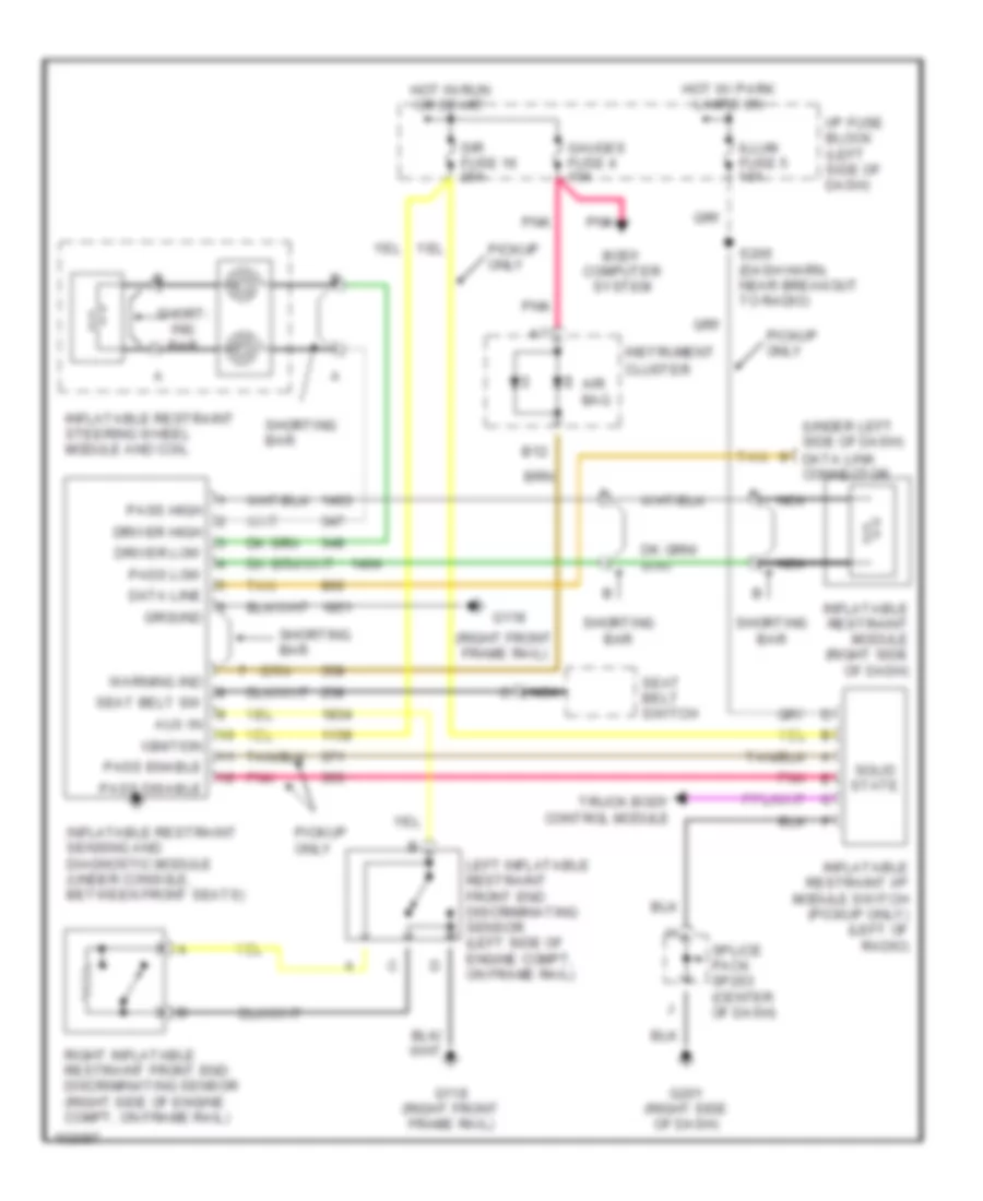
SUPPLEMENTAL RESTRAINTS
Supplemental Restraint Wiring Diagram for GMC Sonoma 1998
List of elements for Supplemental Restraint Wiring Diagram for GMC Sonoma 1998:
- (right front frame rail)
- (under left side of dash) data link connector
- Air bag
- Aux in
- B12
- Bar
- Body computer system
- Cluster
- Data line
- Driver high
- Driver low
- G118
- G118 (right front frame rail)
- G201 (right side of dash)
- Gauges fuse 4 10a
- Ground
- Hot in run or start
- Hot w/ park lamps on
- I/p fuse block (left side of dash)
- Ignition
- Illum fuse 5 10a
- Inflatable restraint i/p module switch (pickup only) (left of radio)
- Inflatable restraint module (right side of dash)
- Inflatable restraint sensing and diagnostic module (under console, between front seats)
- Inflatable restraint steering wheel module and coil
- Instrument
- Left inflatable restraint front end discriminating sensor (left side of engine compt, on frame rail)
- Nca
- Pass disable
- Pass enable
- Pass high
- Pass low
- Pickup only
- Pnk
- Right inflatable restraint front end discriminating sensor (right side of engine compt, on frame rail)
- S205 (dash harn, near breakout to radio)
- Seat belt sw
- Seat belt switch
- Short- ing bar
- Shorting
- Shorting bar
- Sir fuse 16 20a
- Solid state
- Splice pack sp203 (center of dash)
- Tan
- Truck body control module
- Warning ind
 English