TRANSMISSION
2.2L
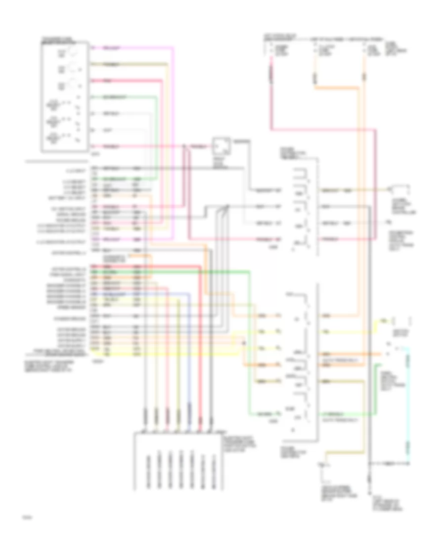
2.2L (VIN 4), Transmission Wiring Diagram, 4L60-E for GMC Sonoma 1994

List of elements for 2.2L (VIN 4), Transmission Wiring Diagram, 4L60-E for GMC Sonoma 1994:
- "high"
- "low"
- (behind i/p, right side of steering column)
- (behind left side of i/p)
- (behind right side of i/p)
- (below i/p, right of steering column)
- (g114: left rear of cylinder head) (g117: right rear of engine)
- (left rear of transmission)
- (left side of cowl, near junction block)
- (on brake pedal support bracket)
- (partial)
- (rear of engine)
- (top front of engine)
- (top rear of engine)
- (vin 4: right side of engine)
- (vin w: top left side of engine)
- (vin z & w) (vin 4)
- 1-2 shift sol
- 1-2 sol control
- 2-3 shift sol
- 2-3 shift sol control
- 20a
- 3-2 control solenoid
- 3-2 sol control
- A15
- A2 a14
- B10
- Battery feed
- Brake fuse 15a
- Brake signal
- C11
- C12
- C13
- Conn 1
- Conn 2
- Cruise control module
- Cruise signal
- Data link connector
- Diagnostic test
- E10
- E13
- E15
- E16
- Ecmb fuse 15a
- Ecmi fuse 10a
- Ect signal
- Electronic 4 - speed overdrive transmission
- Engine coolant temp sensor
- F10
- F12
- F13
- F14
- Force motor
- G114 g117
- Hot at all times
- Hot in run
- Hot in run, bulb
- I/p fuse block
- Ign/gau fuse
- Ignition feed
- Pnk
- Powertrain control module (pcm)
- Range signal "a"
- Range signal "c"
- Range signal"b"
- Red
- Sensor ground
- Serial data
- System gnd
- Tcc sol
- Tcc sol control
- Tcc/brake switch
- Test or start
- Tft signal
- Throttle position sensor (vin z: center left side of engine near throttle body)
- Tp reference
- Tp signal
- Trans out speed
- Trans range press sw assembly
- Trans- mission fluid temp sensor
- Vehicle speed sensor
- Vehicle speed sensor buffer
- Vehicle speed signal
- Vin 4
- Vin 4 & w
- Vin z
- Vin z & w
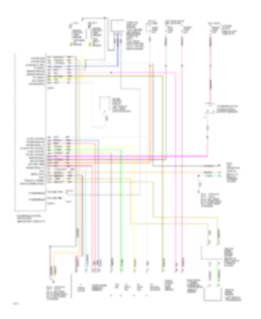
Transfer Case Wiring Diagram for GMC Sonoma 1994
List of elements for Transfer Case Wiring Diagram for GMC Sonoma 1994:
- (auto trans only)
- 12v ignition input
- 2 hi indicator lp output
- 2 hi select
- 2-hi ind
- 2-hi select sw
- 4 hi indicator lp output
- 4 hi select
- 4 lo indicator lp output
- 4 lo input
- 4 lo select
- 4-hi ind
- 4-hi select sw
- 4-lo ind
- 4-lo select sw
- 4wd
- 4wd fuse 20 amp
- 4wheel anti-lock brake controller
- Aux
- Battery 12v input
- C10
- C11
- C12
- C13
- C14
- C15
- C16
- C202a
- C229
- C273
- C289
- C374a
- Chassis ground
- D10
- D11
- D12
- D13
- D14
- D15
- D16
- Diagnostic
- Diagnostic connector
- Elec
- Electric shift transfer case position switch and motor
- Electric shift transfer case control module (behind right side of i/p)
- Encoder channel a
- Encoder channel b
- Encoder channel c
- Encoder channel p
- Encoder channel-a
- Encoder channel-b
- Encoder channel-c
- Encoder channel-p
- Encoder ground
- Front axle switch
- Fuse block (left rear of i/p)
- G112 (left rear of of engine, on cylinder head)
- Gages fuse 20 amp
- Hot at all times
- Hot in run, bulb test or start
- Ignition switch
- Motor control a
- Motor control b
- Motor ground
- Orn
- Park neutral or neutral start switch input
- Park signal input
- Park/ neutral switch (auto trans only)
- Pnk
- Power distribution center a
- Power distribution center b
- Power ground
- Powertrain control module (auto trans only)
- Red
- Shift
- Signal ground
- Speed sensor
- T/l ctsy fuse 20 amp
- Transfer case selector switch
- Vehicle speed sensor buffer (behind right side of i/p)
4.3L
4.3L (VIN W), Transmission Wiring Diagram, 4L60-E for GMC Sonoma 1994
List of elements for 4.3L (VIN W), Transmission Wiring Diagram, 4L60-E for GMC Sonoma 1994:
- "high"
- "low"
- (behind i/p, right side of steering column)
- (behind left side of i/p)
- (behind right side of i/p)
- (below i/p, right of steering column)
- (g114: left rear of cylinder head) (g117: right rear of engine)
- (left rear of transmission)
- (left side of cowl, near junction block)
- (on brake pedal support bracket)
- (partial)
- (rear of engine)
- (top front of engine)
- (top rear of engine)
- (vin 4: right side of engine)
- (vin w: top left side of engine)
- (vin z & w) (vin 4)
- 1-2 shift sol
- 1-2 sol control
- 2-3 shift sol
- 2-3 shift sol control
- 20a
- 3-2 control solenoid
- 3-2 sol control
- A15
- A2 a14
- B10
- Battery feed
- Brake fuse 15a
- Brake signal
- C11
- C12
- C13
- Conn 1
- Conn 2
- Cruise control module
- Cruise signal
- Data link connector
- Diagnostic test
- E10
- E13
- E15
- E16
- Ecmb fuse 15a
- Ecmi fuse 10a
- Ect signal
- Electronic 4 - speed overdrive transmission
- Engine coolant temp sensor
- F10
- F12
- F13
- F14
- Force motor
- G114 g117
- Hot at all times
- Hot in run
- Hot in run, bulb
- I/p fuse block
- Ign/gau fuse
- Ignition feed
- Pnk
- Powertrain control module (pcm)
- Range signal "a"
- Range signal "c"
- Range signal"b"
- Red
- Sensor ground
- Serial data
- System gnd
- Tcc sol
- Tcc sol control
- Tcc/brake switch
- Test or start
- Tft signal
- Throttle position sensor (vin z: center left side of engine near throttle body)
- Tp reference
- Tp signal
- Trans out speed
- Trans range press sw assembly
- Trans- mission fluid temp sensor
- Vehicle speed sensor
- Vehicle speed sensor buffer
- Vehicle speed signal
- Vin 4
- Vin 4 & w
- Vin z
- Vin z & w
4.3L (VIN Z), Transmission Wiring Diagram, 4L60-E for GMC Sonoma 1994
List of elements for 4.3L (VIN Z), Transmission Wiring Diagram, 4L60-E for GMC Sonoma 1994:
- "high"
- "low"
- (behind i/p, right side of steering column)
- (behind left side of i/p)
- (behind right side of i/p)
- (below i/p, right of steering column)
- (g114: left rear of cylinder head) (g117: right rear of engine)
- (left rear of transmission)
- (left side of cowl, near junction block)
- (on brake pedal support bracket)
- (partial)
- (rear of engine)
- (top front of engine)
- (top rear of engine)
- (vin 4: right side of engine)
- (vin w: top left side of engine)
- (vin z & w) (vin 4)
- 1-2 shift sol
- 1-2 sol control
- 2-3 shift sol
- 2-3 shift sol control
- 20a
- 3-2 control solenoid
- 3-2 sol control
- A15
- A2 a14
- B10
- Battery feed
- Brake fuse 15a
- Brake signal
- C11
- C12
- C13
- Conn 1
- Conn 2
- Cruise control module
- Cruise signal
- Data link connector
- Diagnostic test
- E10
- E13
- E15
- E16
- Ecmb fuse 15a
- Ecmi fuse 10a
- Ect signal
- Electronic 4 - speed overdrive transmission
- Engine coolant temp sensor
- F10
- F12
- F13
- F14
- Force motor
- G114 g117
- Hot at all times
- Hot in run
- Hot in run, bulb
- I/p fuse block
- Ign/gau fuse
- Ignition feed
- Pnk
- Powertrain control module (pcm)
- Range signal "a"
- Range signal "c"
- Range signal"b"
- Red
- Sensor ground
- Serial data
- System gnd
- Tcc sol
- Tcc sol control
- Tcc/brake switch
- Test or start
- Tft signal
- Throttle position sensor (vin z: center left side of engine near throttle body)
- Tp reference
- Tp signal
- Trans out speed
- Trans range press sw assembly
- Trans- mission fluid temp sensor
- Vehicle speed sensor
- Vehicle speed sensor buffer
- Vehicle speed signal
- Vin 4
- Vin 4 & w
- Vin z
- Vin z & w
Transfer Case Wiring Diagram for GMC Sonoma 1994
List of elements for Transfer Case Wiring Diagram for GMC Sonoma 1994:
- (auto trans only)
- 12v ignition input
- 2 hi indicator lp output
- 2 hi select
- 2-hi ind
- 2-hi select sw
- 4 hi indicator lp output
- 4 hi select
- 4 lo indicator lp output
- 4 lo input
- 4 lo select
- 4-hi ind
- 4-hi select sw
- 4-lo ind
- 4-lo select sw
- 4wd
- 4wd fuse 20 amp
- 4wheel anti-lock brake controller
- Aux
- Battery 12v input
- C10
- C11
- C12
- C13
- C14
- C15
- C16
- C202a
- C229
- C273
- C289
- C374a
- Chassis ground
- D10
- D11
- D12
- D13
- D14
- D15
- D16
- Diagnostic
- Diagnostic connector
- Elec
- Electric shift transfer case position switch and motor
- Electric shift transfer case control module (behind right side of i/p)
- Encoder channel a
- Encoder channel b
- Encoder channel c
- Encoder channel p
- Encoder channel-a
- Encoder channel-b
- Encoder channel-c
- Encoder channel-p
- Encoder ground
- Front axle switch
- Fuse block (left rear of i/p)
- G112 (left rear of of engine, on cylinder head)
- Gages fuse 20 amp
- Hot at all times
- Hot in run, bulb test or start
- Ignition switch
- Motor control a
- Motor control b
- Motor ground
- Orn
- Park neutral or neutral start switch input
- Park signal input
- Park/ neutral switch (auto trans only)
- Pnk
- Power distribution center a
- Power distribution center b
- Power ground
- Powertrain control module (auto trans only)
- Red
- Shift
- Signal ground
- Speed sensor
- T/l ctsy fuse 20 amp
- Transfer case selector switch
- Vehicle speed sensor buffer (behind right side of i/p)