TRANSMISSION
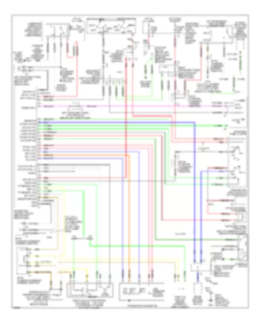
A/T Wiring Diagram, AWD for Pontiac Vibe 2005

List of elements for A/T Wiring Diagram, AWD for Pontiac Vibe 2005:
- (in engine harness, near pcm inside vehicle)
- (inside underhood fuse box)
- (on left side of cylinder head)
- (on left side of cylinder head) g105
- (under left side of dash) data link connector
- (w/ vsc)
- +5v ref
- 2nd brake sol
- Acc
- Anti- lock brakes system
- Battery
- Brake pressure modulator valve (at right front side of engine compt)
- Brake sig
- C11
- C12
- Computer data lines system
- Data link
- Diagnostic
- Ect sens in
- Efi fuse 15a
- Efi relay
- Efi rly control
- Engine controls system
- Engine coolant temperature sensor (left side of cylinder head)
- G103 (at left front strut tower)
- G104
- G105
- G201
- Gauge fuse 10a
- Ground
- Hot at all times
- Hot in run or start
- Ignition
- Ignition switch
- Input shaft speed sensor
- Instrument panel cluster
- Instrument panel fuse block (left of steering column, behind storage compt)
- Interior lights system
- Iss sens hi
- Iss sens lo
- Left instrument panel junction block (behind left side of dash)
- Left instrument panel junction block c2 (behind left side of dash)
- Line pc sol hi
- Line pc sol lo
- Line pressure control solenoid
- Lock
- Logic
- Navigation radio (if equipped)
- O/d ind lamp
- Od indicator
- Od switch in
- Off
- Overdrive switch
- Park/neutral position switch (on transmission)
- Pnk
- Pnp sw 2
- Pnp sw d
- Pnp sw l
- Pnp sw r
- Powertrain control module (behind right side of dash)
- Right instrument panel junction block (behind right c3 side of dash)
- Right instrument panel junction block (behind right side of dash)
- Run
- S100
- S103
- S218
- S229
- S232
- S237
- Sensor gnd
- Serial data
- Shift sol
- Shift sol 1
- Shift sol 2
- Sp107 (in engine harness, near pcm)
- Sp107 (in engine harness, near pcm) c1
- Sp108 (in engine accessory harness, near pcm)
- Sp201 (behind right body hinge pillar trim panel)
- Ss st sol
- Start
- Stop fuse 15a
- Stoplamp switch (behind dash, on brake pedal bracket)
- Tcc sol
- Tft sig
- Throttle position sensor (rear of throttle body)
- Tp sens in
- Transmission connector
- Transmission fluid temperature sensor
- Underhood fuse block (left side of engine compt, on inner fender)
- Vs in
- Vs out
A/T Wiring Diagram, FWD for Pontiac Vibe 2005
List of elements for A/T Wiring Diagram, FWD for Pontiac Vibe 2005:
- (1.8l (vin l): on rear of cylinder head) (1.8l (vin 8): on left side of cylinder head)
- (1.8l vin 8)
- (at left front strut tower) g103
- (at right front side of engine compt) brake pressure modulator valve
- (in engine main harness, inside underhood fuse box) s103
- (lf of engine, attached to throttle body)
- (on transmission) vehicle speed sensor (vss)
- (tac) module
- (w/ vsc)
- (w/o vsc)
- 1.8l (vin 8)
- 1.8l (vin l)
- 2 position sig
- Acc
- Anti-lock brakes system
- Batt pos vol
- Brake sig
- C11
- C12
- Crank sig
- Cruise control release switch
- D position sig
- Ect input
- Efi fuse 15a
- Efi relay
- Efi rly ctrl
- Engine controls system
- Engine coolant temperature sensor (1.8l vin 8: left side of cylinder head) (1.8l vin l: at rear of engine)
- G104 (1.8l (vin l): on rear of cylinder head) (1.8l (vin 8): on left side of cylinder head)
- G105
- G201
- Gauge fuse 10a
- Gnd
- Harness, near pcm inside vehicle)
- Hot at all times
- Hot in run or start
- Ign pos vol
- Ignition switch
- Instrument panel cluster
- Instrument panel fuse block (left of steering column, behind storage compt)
- Interior lights system
- L position sig
- Left instrument panel junction block (behind left side of dash)
- Line pressure control solenoid
- Lock
- Logic
- Navigation radio (if equipped)
- Nca
- Near pcm)
- O/d ind ctrl
- O/d off ind
- O/d on/off sig
- Off
- Overdrive switch
- Park/neutral position switch (on transmission)
- Pc sol high
- Pc sol low
- Pnk
- Powertrain control module (behind right side of dash)
- R position sig
- Red
- Ref vol
- Right instrument panel junction block (behind right c2
- Right instrument panel junction block (behind right c3 side of dash)
- Run
- S110
- S117
- S218
- S222
- S237
- Sensor ground
- Shield
- Shift sol 1
- Shift sol 2
- Side of dash)
- Solid
- Sp107 (in engine accessory harness, near pcm)
- Sp108 (in engine accessory c2 harness, near pcm)
- Sp108 (in engine accessory harness, c1
- Sp108 (in engine accessory harness, near pcm)
- Sp201 (behind right body hinge pillar trim panel)
- Speed input
- Ss 1 ctrl
- Ss 2 ctrl
- Start
- State
- Stop fuse 15a
- Stoplamp switch (behind left side of dash, on brake pedal support bracket)
- Tac motor
- Tac mtr ctrl hi
- Tac mtr ctrl lo
- Tcc ctrl
- Tcc sol
- Throttle actuator control
- Throttle position sensor (on rear of throttle body)
- Tp sensor
- Tp sensor 1 sig
- Tp sensor 2 sig
- Transmission connector
- Underhood fuse block (left side of engine compt, mounted to inner fender)
- Vs in
- Vs out
- W/ abs
- W/o abs
 English