AIR CONDITIONING
Manual A/C Wiring Diagram (1 of 2) for Scion xA 2005

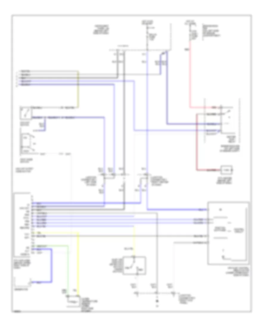
List of elements for Manual A/C Wiring Diagram (1 of 2) for Scion xA 2005:
- (at left front of engine compt)
- (behind left side of dash) instrument panel j/b
- (left end of dash)
- (lower right side of dash) blower motor
- (right kick panel) ig
- (right side of engine compt)
- A/c 2 fuse 7.5a
- A/c condenser fan resistor (left front of engine compt, behind headlight)
- A/c fuse 7.5a
- A/c magnetic valve (lower right front of engine)
- A/c thermistor (right side of dash)
- A11
- Ac1
- Acc
- Blower resistor (behind right side of dash)
- Center cluster switch
- Defroster mode detection switch (inside switch)
- Dual
- E5 (left side of engine compt)
- Ea (right rear of engine compt)
- Ec (left top of engine)
- Ed (right rear of engine compt)
- Efi fuse 15a
- Efi relay
- Engine control module (behind lower right side of dash)
- Engine coolant temperature sensor (on left front of engine)
- Engine room r/b (on left side of engine compartment)
- Engine room r/b (on left side of engine compt)
- Fan
- Fan 1 relay
- Fan 2 relay
- Gauge fuse 10a
- Gnd
- H18
- Heater relay
- Hot at all times
- Hot in on or start
- Htr fuse 40a
- I4 (lower center of dash)
- I7 (right side of dash)
- Ie (left kick panel)
- Ignition switch
- Instrument panel j/b (behind left side of dash)
- Junction connector (left side of dash)
- Junction connector 8 (right kick panel)
- Lock
- Mgv
- Mhsw
- Off
- Pressure switch (right side of engine)
- Ptc1
- Radiator fan motor
- Rdef
- Rdi fuse 30a
- Single
- Start
- Tach
- Thr
- Thw
Manual A/C Wiring Diagram (2 of 2) for Scion xA 2005
List of elements for Manual A/C Wiring Diagram (2 of 2) for Scion xA 2005:
- Air inlet control servo motor (under upper right side of dash)
- Alt
- Control circuit
- Ecu-ig fuse 7.5a
- Engine room r/b (on left side of engine compartment)
- Engine room r/b (on left side of engine compt)
- F/d
- Foot
- Foot mode switch
- Frs
- G10
- Generator
- Gnd
- H11
- Heater sub 1 relay
- Hot at all times
- Hot in on or start
- Htr sub 1 fuse 50a
- Inlet air position detection switch (inside switch)
- Instrument panel j/b (behind left side of dash)
- Junction connector 3 (left side of dash)
- Junction connector 7 (right center of dash)
- Junction connector 8 (right kick panel)
- Max hot
- Max hot & foot mode switch
- Max hot switch
- Mode in
- Position switches
- Ptc amplifier (behind upper right side of dash)
- Ptc heater (behind left side of dash)
- Ptc1
- R/f1
- Rec
- Rec/frs
- Red
- Tw1
- Water temperature sensor (upper right side of dash)