ANTI-LOCK BRAKES
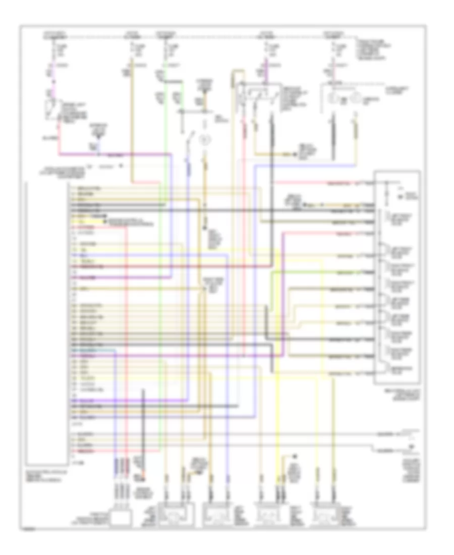
Anti-lock Brakes Wiring Diagram for BMW 318ti 1999
List of elements for Anti-lock Brakes Wiring Diagram for BMW 318ti 1999:
- (below left side of dash) g202
- (right side of glove box) g201
- Abs hydraulic unit (left rear of engine compt)
- Abs ind
- Abs pump motor relay (in front power distributon box)
- Asc switch
- Auxiliary throttle position motor (near air cleaner)
- Brake light switch (on bracket, above brake pedal)
- Data link connector (on left rear of engine compartment)
- Engine controls systems
- Engine controls, transmissions systems
- Exterior lights system
- Front power distribution box (left rear corner of engine compt)
- Fuse f10 30a
- Fuse f21 5a
- Fuse f27 5a
- Fuse f38 30a
- Fuse f46 15a
- G201 (right side of glove box)
- Hot at all times
- Hot in accy, run & start
- Hot in run & start
- Instrument cluster
- Interior lights system
- Left front abs speed sensor
- Left front solenoid valve
- Left rear abs speed sensor
- Left rear solenoid valve
- Nca
- Pump motor
- Right front abs speed sensor
- Right front solenoid valve
- Right rear abs speed sensor
- Right rear solenoid valve
- Separating valve
- Slip control module (abs/asc) (behind glove box)
- Throttle position sensor (on throttle body)
- Warning ind
- X10015
- X10017
- X10018
- X11395
- X1170
- X16
 English